Download
1 / 1
10 likes | 134 Views
LISA STUDIES AT THE UNIVERSITY OF COLORADO. Michael J. Nickerson, Ellery B. Ames, John L. Hall, and Peter L. Bender JILA, University of Colorado and NIST, Boulder, CO. Current LISA Projects at JILA. Dual-Cylinder Laser Reference Cavity Design. Laser Reference Cavity. Cavity Construction.

E N D
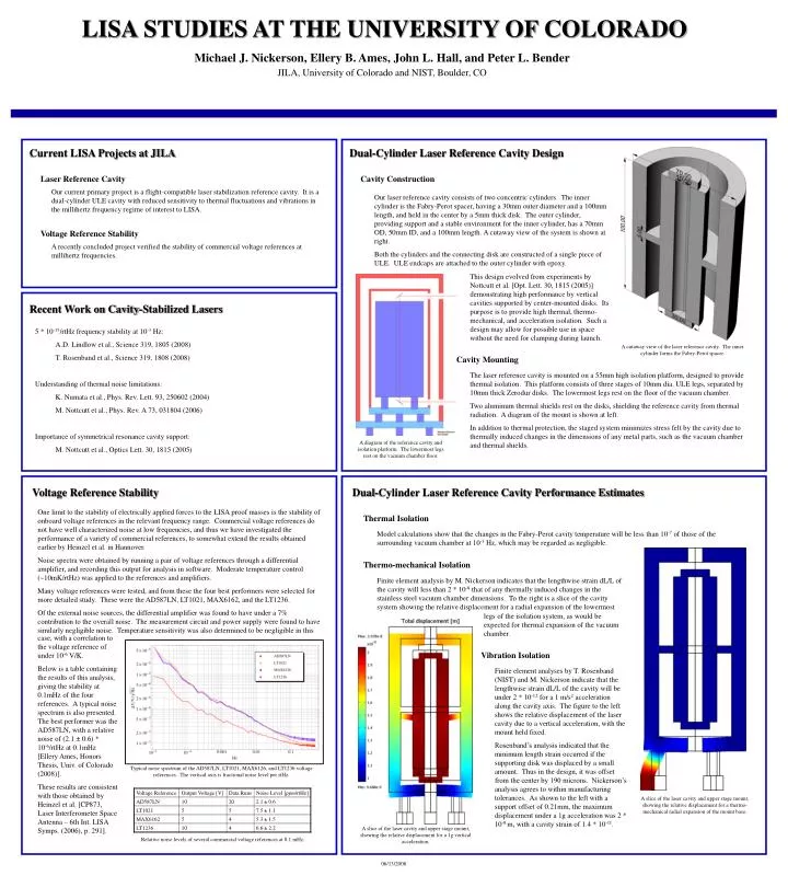
LISA STUDIES AT THE UNIVERSITY OF COLORADO Michael J. Nickerson, Ellery B. Ames, John L. Hall, and Peter L. Bender JILA, University of Colorado and NIST, Boulder, CO Current LISA Projects at JILA Dual-Cylinder Laser Reference Cavity Design Laser Reference Cavity Cavity Construction Our current primary project is a flight-compatible laser stabilization reference cavity. It is a dual-cylinder ULE cavity with reduced sensitivity to thermal fluctuations and vibrations in the millihertz frequency regime of interest to LISA. Our laser reference cavity consists of two concentric cylinders. The inner cylinder is the Fabry-Perot spacer, having a 30mm outer diameter and a 100mm length, and held in the center by a 5mm thick disk. The outer cylinder, providing support and a stable environment for the inner cylinder, has a 70mm OD, 50mm ID, and a 100mm length. A cutaway view of the system is shown at right. Both the cylinders and the connecting disk are constructed of a single piece of ULE. ULE endcaps are attached to the outer cylinder with epoxy. Voltage Reference Stability A recently concluded project verified the stability of commercial voltage references at millihertz frequencies. This design evolved from experiments by Nottcutt et al. [Opt. Lett. 30, 1815 (2005)] demonstrating high performance by vertical cavities supported by center-mounted disks. Its purpose is to provide high thermal, thermo-mechanical, and acceleration isolation. Such a design may allow for possible use in space without the need for clamping during launch. Recent Work on Cavity-Stabilized Lasers 5 * 10-15/rtHz frequency stability at 10-3 Hz: A.D. Lindlow et al., Science 319, 1805 (2008) T. Rosenband et al., Science 319, 1808 (2008) Understanding of thermal noise limitations: K. Numata et al., Phys. Rev. Lett. 93, 250602 (2004) M. Nottcutt et al., Phys. Rev. A 73, 031804 (2006) Importance of symmetrical resonance cavity support: M. Nottcutt et al., Optics Lett. 30, 1815 (2005) A cutaway view of the laser reference cavity. The inner cylinder forms the Fabry-Perot spacer. Cavity Mounting The laser reference cavity is mounted on a 55mm high isolation platform, designed to provide thermal isolation. This platform consists of three stages of 10mm dia. ULE legs, separated by 10mm thick Zerodur disks. The lowermost legs rest on the floor of the vacuum chamber. Two aluminum thermal shields rest on the disks, shielding the reference cavity from thermal radiation. A diagram of the mount is shown at left. In addition to thermal protection, the staged system minimizes stress felt by the cavity due to thermally induced changes in the dimensions of any metal parts, such as the vacuum chamber and thermal shields. A diagram of the reference cavity and isolation platform. The lowermost legs rest on the vacuum chamber floor. Voltage Reference Stability Dual-Cylinder Laser Reference Cavity Performance Estimates One limit to the stability of electrically applied forces to the LISA proof masses is the stability of onboard voltage references in the relevant frequency range. Commercial voltage references do not have well characterized noise at low frequencies, and thus we have investigated the performance of a variety of commercial references, to somewhat extend the results obtained earlier by Heinzel et al. in Hannover. Noise spectra were obtained by running a pair of voltage references through a differential amplifier, and recording this output for analysis in software. Moderate temperature control (~10mK/rtHz) was applied to the references and amplifiers. Many voltage references were tested, and from these the four best performers were selected for more detailed study. These were the AD587LN, LT1021, MAX6162, and the LT1236. Of the external noise sources, the differential amplifier was found to have under a 7% contribution to the overall noise. The measurement circuit and power supply were found to have similarly negligible noise. Temperature sensitivity was also determined to be negligible in this Thermal Isolation Model calculations show that the changes in the Fabry-Perot cavity temperature will be less than 10-7 of those of the surrounding vacuum chamber at 10-3 Hz, which may be regarded as negligible. Thermo-mechanical Isolation Finite element analysis by M. Nickerson indicates that the lengthwise strain dL/L of the cavity will less than 2 * 10-8 that of any thermally induced changes in the stainless steel vacuum chamber dimensions. To the right is a slice of the cavity system showing the relative displacement for a radial expansion of the lowermost legs of the isolation system, as would be expected for thermal expansion of the vacuum chamber. case, with a correlation to the voltage reference of under 10-6 V/K. Below is a table containing the results of this analysis, giving the stability at 0.1mHz of the four references. A typical noise spectrum is also presented. The best performer was the AD587LN, with a relative noise of (2.1 ± 0.6) * 10-6/rtHz at 0.1mHz [Ellery Ames, Honors Thesis, Univ. of Colorado (2008)]. These results are consistent with those obtained by Heinzel et al. [CP873, Laser Interferometer Space Antenna – 6th Int. LISA Symps. (2006), p. 291]. Vibration Isolation Finite element analyses by T. Rosenband (NIST) and M. Nickerson indicate that the lengthwise strain dL/L of the cavity will be under 2 * 10-12 for a 1 m/s2 acceleration along the cavity axis. The figure to the left shows the relative displacement of the laser cavity due to a vertical acceleration, with the mount held fixed. Rosenband’s analysis indicated that the minimum length strain occurred if the supporting disk was displaced by a small amount. Thus in the design, it was offset from the center by 190 microns. Nickerson’s analysis agrees to within manufacturing tolerances. As shown to the left with a support offset of 0.21mm, the maximum displacement under a 1g acceleration was 2 * 10-8 m, with a cavity strain of 1.4 * 10-11. Typical noise spectrum of the AD587LN, LT1021, MAX6126, and LT1236 voltage references. The vertical axis is fractional noise level per rtHz. A slice of the laser cavity and upper stage mount, showing the relative displacement for a thermo-mechanical radial expansion of the mount base. A slice of the laser cavity and upper stage mount, showing the relative displacement for a 1g vertical acceleration. Relative noise levels of several commercial voltage references at 0.1 mHz. 06/13/2008