Download
1 / 20
200 likes | 341 Views
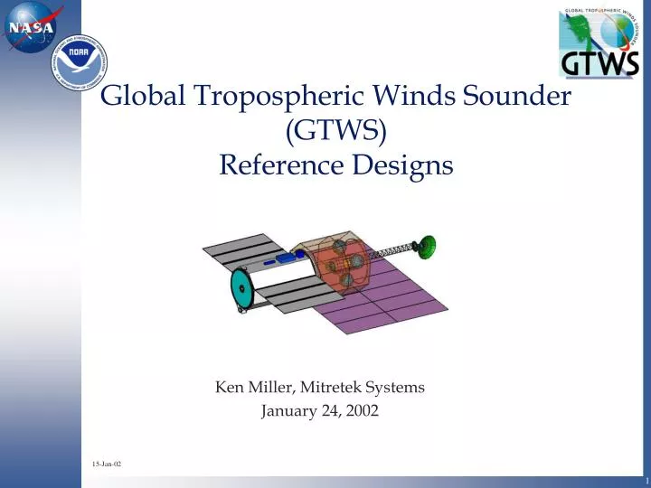
Global Tropospheric Winds Sounder (GTWS) Reference Designs. Ken Miller, Mitretek Systems January 24, 2002. 15-Jan-02. Agenda. GTWS Mission Objective Purpose Draft Wind Data Product Requirements Rapid Design Reference Instruments Reference Missions Direct Mission Conclusions

E N D
Global Tropospheric Winds Sounder(GTWS)Reference Designs Ken Miller, Mitretek Systems January 24, 2002 15-Jan-02
Agenda • GTWS Mission Objective • Purpose • Draft Wind Data Product Requirements • Rapid Design • Reference Instruments • Reference Missions • Direct Mission • Conclusions • Acknowledgments
Purpose • Mission Objective is to acquire global wind velocity profiles per NASA/NOAA requirements • Purpose of Briefing is to discuss Government Reference Designs for • Direct and Coherent Instruments • Direct Mission • Coherent Mission design scheduled Feb 2002
Purpose of Reference Designs • To establish instrument and mission architectures for reference purposes • Identify tall poles (technology readiness and risk) • Provide information to support a basis for government cost estimate • Provide sanity check information for assessing future concepts • It is not assumed that future implementations will physically match study results
Draft Wind Data ProductRequirements • Threshold and Desired requirements prepared by the GTWS Science Definition Team (SDT) • Reconciled between NASA and NOAA users • Threshold requirements were minimum for useful impact on models • Posted for comment Oct 16, 2001 http://nais.msfc.nasa.gov/cgi-bin/EPS/sol.cgi?acqid=99220#Draft Document • See Yoe/Atlas presentation
Rapid Design Environmentsat NASA GSFC • ISAL • Instrument Synthesis and Analysis Laboratory • Rapid instrument design and concepts for remote sensing • 2 week GTWS studies • IMDC • Integrated Mission Development Center • Rapid mission engineering analyses and services • Concepts, trades, technology and risk assessment • 1 week GTWS studies
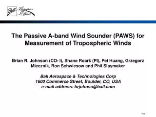
Reference Instruments • Direct and Coherent lidars • Meet threshold data requirements, including • 0 to 20 km altitude • Target Sample Volume (TSV) • Maximum volume for averaging laser shots • 2 perspectives per TSV • Reference atmosphere including cloud coverage and shear • 2 year mission life • Exceptions • Single laser designs may not meet lifetime requirement • Single satellite did not meet temporal resolution requirement
Reference Instruments (cont’d) • Do not provide • Implementation recommendations or preferences • Exhaustive technology trades • Basis to compare direct and coherent approaches • General limitations • Based on first-cut point designs, not optimized • Numerous assumptions need verification • Low TRL components • May not meet all requirements • Requirements refined during design period • Some details are competition sensitive
Reference Instruments-Design • GTWS Team guidance on point designs • Direct– Bruce Gentry (NASA GSFC), Sept 2001 • Coherent– Michael Kavaya (NASA LaRC), Dec 2001 • Parameters • 400 km circular orbit, 97o inclination, sun synchronous, dawn/dusk • 100% duty cycle • Nadir angle 45 o • Scan discrete azimuth angles • Point (~ 1 s) and Stare (~ 5 s) • 4 cross-track soundings, 4 positions fore, 4 aft
Measurement Concept 7.7 km/s • Vertical resolution range gates • 45 o nadir angle • Scan through 8 azimuth angles • Fore and aft perspectives in TSV • Move scan position ~ 1 sec • No. shots averaged ~ 5 sec * prf Aft perspective 45° 585 km 400 km 45° Horizontal TSV 414 km 7.2 km/s 290 km 290 km
Reference Instruments -Concepts Solar Array (Radiator not shown) Belt Drive Telescope with Sunshade Rotating Deck Component Boxes Direct Radiator (Solar Array not shown) Component Housing Coherent
Direct MissionHighlights • IMDC • Direct - October 2001 • Coherent - February 2002 • Large, heavy spacecraft with high power requirements • 400 km orbit is challenging • Altitude tradeoff between lidar SNR and orbit maintenance • Solar array & radiator in orbital plane to reduce drag • Battery power during eclipse (max 25 min/day) • Delta 2920-10L, long fairing option • Current technology spacecraft • Conventional hydrazine propulsion
Direct MissionHighlights (concluded) • TDRSS Demand Access Downlink • Controlled disposal at end-of-life • COTS-based Mission Operations Center, 8x5 operations • Data System • Internal computer • 70 Gbits storage for 3 days
Direct Mission - Deployed Configuration Concept SC Bus Instrument Radiator TDRS Antenna Belt Drive Rotating Mechanism Solar Array
Direct MissionTechnology Readiness Level (TRL) • Low instrument TRL: development, test, and demonstration are needed • Spacecraft Overall TRL: 6 • Definitions • TRL 6: System/subsystem model or prototype demonstration in a relevant environment (ground or space) • TRL 7: System prototype demonstration in a space environment • TRL 8: Actual system completed and "flight qualified" through flight test demonstration (ground or space)
Conclusions • Mass, size, and power are very large • Need to increase instrument TRL • Assumed lasers are well beyond current on-orbit laser power, efficiency, and lifetime • Desirable laser improvements • Increase optical output to reduce telescope size and mass • Increase efficiency to reduce power and heat • Increase life expectancy • Increase DWL experience across range of atmospheric conditions • Reduce risk: • Scanner • Momentum compensation • Lag angle compensation • Other areas
Conclusions (cont’d) • Still a lot to learn and assess - including • Fundamental differences between data products from direct and coherent lidars • Global cloud and aerosol distributions • Data product impacts from • Clouds • Aerosol distribution • Wind shear • Solar backscatter • Spacecraft pointing and jitter
Acknowledgments • NASA • Farzin Amzajerdian, Coherent Lidar Engineer, f.amzeajerdian@larc.nasa.gov • Robert Atlas, Science Definition Team Lead, robert.m.atlas.1@gsfc.nasa.gov • James Barnes, GTWS Program Executive, j.c.barnes@larc.nasa.gov • Jennifer Bracken, ISAL Team Lead, jennifer.bracken@gsfc.nasa.gov • Dave Emmitt, Senior Scientist, gde@swa.com • Bruce Gentry, Direct Lidar Principal Investigator, bruce.m.gentry.1@gsfc.nasa.gov • Gabe Karpati, IMDC Systems Engineer, gkarpati@pop700.gsfc.nasa.gov • Michael Kavaya, Coherent Lidar Principal Investigator, m.j.kavaya@larc.nasa.gov • John Martin, IMDC Team Lead, jmartin@pop400.gsfc.nasa.gov • Ken Miller, Systems Engineer, kenm@mitretek.org • Mike Roberto, ISAL Systems Engineer, mroberto@pop700.gsfc.nasa.gov • GTWS Team • IMDC Teams • ISAL Team • NOAA • John Pereira, Program Manager, john.pereira@noaa.gov • James Yoe, Science Definition Team Lead, james.g.yoe@noaa.gov