Download
1 / 2
20 likes | 151 Views
SYSTEM INTEGRATION N+1 PASSIVE STANDBY CONFIGURATION. The passive N+1 Standby configuration comprises only one standby transmitter for all active transmitters, the N+1 Control Unit as well as AF and RF switches.

E N D
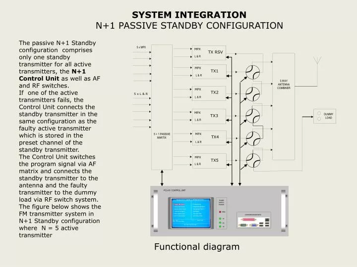
SYSTEM INTEGRATION N+1 PASSIVE STANDBY CONFIGURATION The passive N+1 Standby configuration comprises only one standby transmitter for all active transmitters, the N+1 Control Unit as well as AF and RF switches. If one of the active transmitters fails, the Control Unit connects the standby transmitter in the same configuration as the faulty active transmitter which is stored in the preset channel of the standby transmitter. The Control Unit switches the program signal via AF matrix and connects the standby transmitter to the antenna and the faulty transmitter to the dummy load via RF switch system. The figure below shows the FM transmitter system in N+1 Standby configuration where N = 5 active transmitter 5 x MPX MPX TX RSV L & R MPX TX1 L & R 5 WAY ANTENNA COMBINER MPX TX2 5 x L & R L & R MPX DUMMY LOAD TX3 L & R MPX 5 + 1 PASSIVE MARTIX TX4 L & R MPX TX5 L & R Functional diagram
N+1 PASSIVE STANDBY CONFIGURATION 5 x 10kW FM Transmitting Equipment employing 5+1 TX Standby System