Download
1 / 12
120 likes | 265 Views
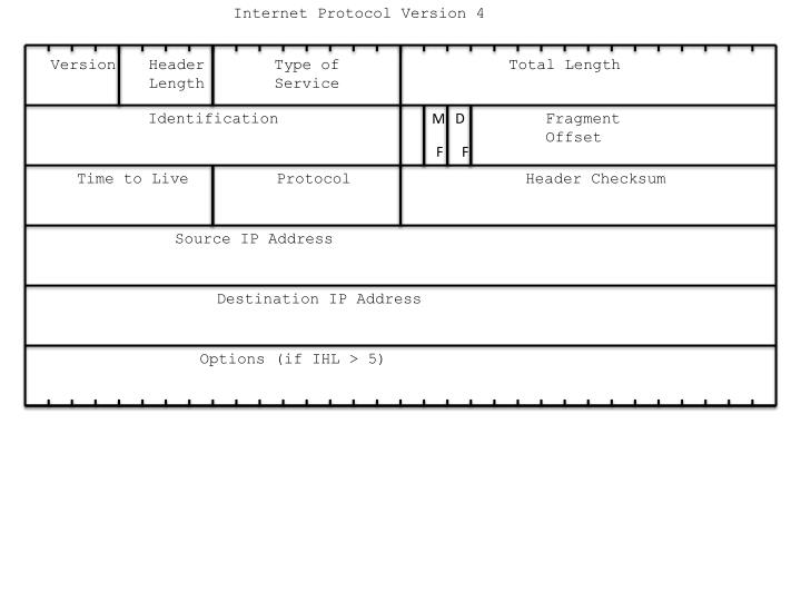
Internet Protocol Version 4. Version. Header Length. Type of Service. Total Length. D. Identification. M. Fragment Offset. F. F. Time to Live. Protocol. Header Checksum. Source IP Address. Destination IP Address. Options (if IHL > 5). IP Header: ( IPV4). 31 (Bits). 0. 4. 8.

E N D
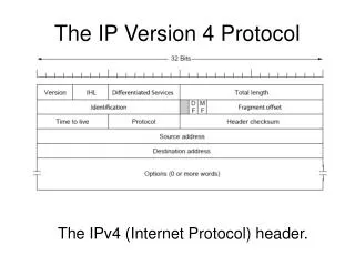
Internet Protocol Version 4 Version Header Length Type of Service Total Length D Identification M Fragment Offset F F Time to Live Protocol Header Checksum Source IP Address Destination IP Address Options (if IHL > 5)
IP Header:( IPV4) 31 (Bits) 0 4 8 19 16 Type of Service Version IHL Total Length Flags Identification Fragment Offset Time to Live Protocol Header Checksum 20 Bytes Source Address Destination Address Options + Padding
IP Header Details: • Version ( 4 Bits ) - version number now is 4 • Internet Header Length (IHL) (4 Bits) - length of IP header in 32 bit words. Minimum value is 5 for a minimum header of 20 bytes. When option field max size, IHL = 15 • Type of service (8 bits) 3 Bits Precedence 4 Bits TOS One Bit Not used at present 0000 normal service 0001 minimize cost 0010 maximize reliability 1000 minimize delay • Total Length (16 Bits) - Total IP datagram length in bytes including IP header. Maximum length value is 216-1 = 65,535
It is possible to have an IP datagram that is too big for some networks.For example, the Maximum Transfer Unit (MTU) of data that may be encapsulated into an ethernet frame is 1,500 bytes. If we have an IP datagram larger than this, we will have to fragment the datagram. • This means breaking the datagram into smaller pieces. The header is copied for use in every fragment. The flags, fragmentation offset, and the total length fields are set to new values in each fragment. • Identification (16 Bits) - a sequence number. Counter in the source machine keeps track of how many IP datagrams it has sent. This value is copied into the identification field. Fragments all have the same identification number. • Flags ( 3 Bits ) • •More Bit - when datagram is fragmented this bit indicates if this is the last fragment. A • value of one indicates there are more fragments, a value of zero means this is the end. • •Do not fragment bit - do not fragment if this bit is a one • •Unused bit • Fragment Offset (13 Bits) - where in the original datagram this fragment belongs measured in 64 bit units. This means divide the offset location in bytes by 8 to get the value in the header. Conversely multiply the value you see in a header before you use it. Since offset field is only 13 bits, use this divide/multiply by 8 method to allow larger than 213-1 offsets
Example: Given a 3,500 byte IP datagram and an ethernet network with an Maximum Transfer Unit = 1,500 bytes. Assume there are no options included in the 20 byte IP header. We have 3,500 total bytes – 20 header bytes = 3,480 data bytes to transport. The MTU limit = 1,500 so the largest a data payload may be is 1,500 – 20 header = 1480 The amount of data we carry must be a multiple of 8 because of the offset field definition. 184 * 8 = 1,472 185 * 8 = 1,480 186 * 8 = 1,488 We should choose 1,480 data bytes in the first segment so that the total size is 1480 data plus 20 header = 1,500 which is equal to or less than the MTU of 1,500. The offset field will have the value 0, the more flag will be equal to 1. The second datagram will also carry 1,480 bytes with the offset field equal to 1480/8= 185. The more flag will be equal to 1 The third datagram will carry the remaining 3,480 – (1,480 + 1,480) = 520 bytes. It will be carried in an IP datagram with 520 + 20 Overhead bytes = 540 bytes. The offset field will be (1,480+1,480) / 8 )=370, and the more flag will equal 0.
In the event a fragment is itself fragmented, then the offset value used is relative to the original datagram prior to any fragmentation. Example: Suppose that second datagram in the previous example (which is 1,500 bytes in size) is further fragmented into two fragments because we encounter a smaller MTU = 766. The resulting new fragments for the second fragmented datagram from our original example are: For an MTU of 766 we may have a max of 766 – 20 overhead = 746 data bytes. 746/8 = 93.25 so we should use 93*8 = 744 data bytes in one new segment, leaving 1480 total data – 744 in one segment = 736 data left for next segment. So First additional segment has 744 + 20 = 764 bytes total, offset value = same old start of 185 from before. Next additional segment has 736 + 20 = 756 bytes total, new offset = 185 + 744/8 = 185 + 93 = 278. Note that the offset value is relative to the relative position of the data to the original (source) data.
IP Header Details: • Time To Live (8 Bits) - how long datagram exists usually done by hop count. Every router decreases TTL by at least one. • Protocol (8 Bits) - indicates next higher level protocol IE TCP, UDP, ICMP, IGMP, etc 1 ICMP Internet Control Message Protocol 2 IGMP Internet Group Message Protocol 6 TCP Transmission Control Protocol 17 UDP User Datagram Protocol 41 IPV6 89 OSPF Open Shortest Path First Routing Protocol • IP Header Checksum (16 Bits ) - applied to header only. At the sender the checksum field is first set to zero, then the header is divided into 16 bit pieces. These pieces are added together using one’s complement arithmetic with a result that is also 16 bits long. The sum is complemented (inverted). This is the check sum value put in the datagram header. At the receiver, the 16 bit pieces are once again added using ones complement arithmetic. If there are no errors in the header, the complemented result will be all zeros.
IP Checksum Calculation Example: Given the following IP Header, calculate the IP checksum value. 4 5 0 64 4, 5, and 0 64 2 0 and 0 16 and 17 255 and 255 0 and 0 1 and 1 0 and 0 SUM CHECKSUM 0 1 0 0 0 1 0 1 0 0 0 0 0 0 0 0 0 0 0 0 0 0 0 0 0 1 0 0 0 0 0 0 0 0 0 0 0 0 0 0 0 0 0 0 0 0 1 0 0 0 0 0 0 0 0 0 0 0 0 0 0 0 0 0 0 0 0 1 0 0 0 0 0 0 0 1 0 0 0 1 1 1 1 1 1 1 1 1 1 1 1 1 1 1 1 1 0 0 0 0 0 0 0 0 0 0 0 0 0 0 0 0 0 0 0 0 0 0 0 1 0 0 0 0 0 0 0 1 0 0 0 0 0 0 0 0 0 0 0 0 0 0 0 0 01 0 1 0 1 1 0 0 1 0 1 0 1 0 0 1 0 1 0 1 0 0 1 1 0 1 0 1 0 1 1 2 0 0 16 17 You are calculating this 255.255.0.0 1.1.0.0 (This example had a 1 end around carry added back to the solution)
Source Address - (32 Bits ) • Destination Address - (32 Bits ) • Options(Variable) • Padding(Variable) - used so header always multiple of 4 Bytes. • Data(Variable) - max length including header 65, 535 • Option bytes may or may not exist. If they do exist they look like this:
IP Options: Single Byte: No Operation 00000001 End of Options 00000000 Multiple Byte Varying in Length: Record Route Strict Source Routing Loose Source Routing Timestamp
Code Field Copy 1 Bit Class 2 bits Type 5 bits Length 8 bits Data field is of variable length The Copy Bit: 0 Copy only in the first fragment 1 Copy into all fragments The Class Bits: 00 Datagram Control 10 Debugging and Management The Type Bits: 00000 End of Operation 00001 No Operation 00011 Loose Source Routing 00100 Timestamp 00111 Record Route 01001 Strict Source Route
Example Loose Source Route Option: Code Field NO OP 00000001 10000011 Total Length Integer Pointer Value First IP address Second IP address . . . Last IP address Note that these 4 byte words would be appended to the end of the IP header just before the data. That is where options are put. A No Operation byte is a filler byte to make it so that options are always a multiple of 4 bytes. Pointer is an integer number to the first empty byte in this option field. Makes more sense in an option that fills in fields as you go along.