Download
1 / 25
250 likes | 375 Views
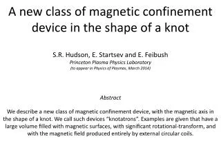
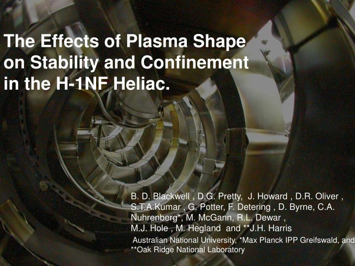
The Effects of Plasma Shape on Stability and Confinement in the H-1NF Heliac. B. D. Blackwell , D.G. Pretty, J. Howard , D.R. Oliver , S.T.A.Kumar , G. Potter, F. Detering , D. Byrne, C.A. Nuhrenberg*, M. McGann, R.L. Dewar , M.J. Hole , M. Hegland and **J.H. Harris

E N D
The Effects of Plasma Shape on Stability and Confinement in the H-1NF Heliac. B. D. Blackwell , D.G. Pretty, J. Howard , D.R. Oliver , S.T.A.Kumar , G. Potter, F. Detering , D. Byrne, C.A. Nuhrenberg*, M. McGann, R.L. Dewar , M.J. Hole , M. Hegland and **J.H. Harris Australian National University, *Max Planck IPP Greifswald, and **Oak Ridge National Laboratory
Outline H-1 Heliac Configurations, parameters, diagnostics MHD Data Data mining, SVD Interpretation Alfvénic Scaling H-1’s unique twist control as an additional fit parameter Scaling discrepancies Radial Structure Confinement Effects Summary
H-1NF: National Plasma Fusion Research Facility A Major National Research Facility established in 1997 by the Commonwealth of Australia and the Australian National University Mission: • Detailed understanding of the basic physics of magnetically confined hot plasma in the HELIAC configuration • Development of advanced plasma measurement systems • Fundamental studies including turbulence and transport in plasma • Contribute to global research effort, maintain Australian presence in the field of plasma fusion power The facility is available to Australian researchers through the AINSE1 and internationally through collaboration with Plasma Research Laboratory, ANU. 1) Australian Institute of Nuclear Science and Engineering Contract extended until 2010: includes some operational funding and limited collaborative funding International collaboration played an important role in the success of H-1 in obtaining facility funding
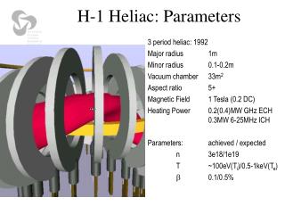
H-1 Heliac: Parameters 3 period heliac: 1992 Major radius 1m Minor radius 0.1-0.2m Vacuum chamber 33m2 excellent access Aspect ratio 5+ toroidal Magnetic Field 1 Tesla (0.2 DC) Heating Power 0.2MW 28 GHz ECH 0.3MW 6-25MHz ICH Parameters: achieved to date::expected n3e18 :: 1e19 T<200eV(Te)::500eV(Te) 0.1 :: 0.5%
H-1 configuration (shape) is very flexible • “flexible heliac” : helical winding, with helicity matching the plasma, 2:1 range of twist/turn • H-1NF can control 2 out of 3 oftransform () magnetic well and shear (spatial rate of change) • Reversed Shear Advanced Tokamak mode of operation low shear = 4/3 = 5/4 medium shear Edge Centre
Large Device Physics on H-1 D3D tokamak H-1 Confinement Transitions, Turbulence (Shats, 1996--) • High Confinement mode (’96) • Zonal Flows 2001 • Spectral condensation of turbulence 2005 Magnetic Island Studies • H-1 has flexible, controlled and verified geometry • Create islands in desired locations (shear, transform) • Langmuir probes can map in detail Alfvén Eigenmodes • May be excited in reactors by fusion alphas, and destroy their confinement • (more)
Plasma Production by ICRF • ICRF Heating: • B=0.5Tesla, = CH (f~7Mhz) • Large variation in ne with iota Backward WaveOscillator Scanning Interferometer (Howard, Oliver) time Axis
Configuration scan: rich in detail D. Pretty, J. Harris 5/4 7/5 4/3 ICRF plasma configuration scan Mode spectrum changes as resonances enter plasma No simple explanation for “gap” left side corresponds to zero shear at resonance A clear connection with rational twists per turn – but what is it? increasing twist Plasma density gap 4/3 7/5 5/4 increasing twist
Magnetic fluctuations approach “high temperature” conditions: H, He, D; B ~ 0.5T; ne ~ 1e18; Te<50eVi,e<< a, mfp >> conn • spectrum in excess of 5-100kHz • Low mode numbers: m ~ 0 - 7, n ~ 0 - 9 • b/B ~ 2e-4 • both broad-band and coherent/harmonic nature • abrupt changes in spectrum randomly or correlated with plasma events
Python open source datamining tools David Pretty: http://code.google.com/p/pyfusion
Identification with Alfvén Eigenmodes: ne phase • Coherent mode near iota = 1.4, 26-60kHz, Alfvénic scaling with ne • m number resolved by bean array of Mirnov coils to be 2 or 3. • VAlfvén = B/(o) B/ne • Scaling in ne in time (right) andover various discharges (below) 1/ne ne f 1/ne Critical issue in fusion reactors: VAlfvén ~ fusion alpha velocity fusion driven instability!
Mode Decomposition by SVD and Clustering Data mining • 4 Gigasamples of data • 128 times • 128 frequencies • 2C20 coil combinations • 100 shots • Initial decomposition by SVD ~10-20 eigenvalues • Remove low coherence and low amplitude • Then group eigenvalues by spectral similarity into fluctuation structures • Reconstruct structuresto obtain phase difference at spectral maximum • Cluster structures according to phase differences (m numbers) reduces to 7-9 clusters for an iota scan Grouping by SVD+clustering potentially more powerful than by mode number • Recognises mixturesof mode numbers caused by toroidal effects etc • Does not depend critically on knowledge of thecorrect magnetic theta coordinate increasing twist
Mode numbers consistent with twist • Mode analysis of the clusters found is complex, but is consistent with the rotational transform (twist/turn) dominant toroidal mode n=4 (aliased to n=1) Iota=4/3 dominant azimuthal m=3
Identification with Alfvén eigenmodes: k||, twist Small near resonance Why is f so low? VAlfven~ 5x10⁶ m/s • res = k||VAlfvén = k||B/(o) • k|| varies as the angle between magnetic field lines and the wave vector • for a periodic geometry the wave vector is determined by mode numbers n,m • Component of k parallel to B is - n/m k|| = (m/R0)( - n/m) res = (m/R0)( - n/m)B/(o) • Low shear means relatively simple dispersion relations – advantage of H-1 Alfvén dispersion (0-5MHz) Alfvén dispersion (0-50kHz) Near rationals, resonant freq. is low
Identification with Alfvén eigenmodes k|| 0 as twist n/m = 4/3 ota David Pretty res = k||VA = (m/R0)( - n/m)B/(o) • k|| varies as the angle between magnetic field lines and the wave vector k|| - n/m • iota resonant means k||, 0 Expect Fresto scale with iota Resonant Twist
Two modes coexisting at different radii Cross-power between ne and Mirnov coils shows two modes coexisting (0,180o) Probably at different radii as frequency is different, mode numbers the same
CAS3D: 3D and finite beta effects Carolin Nuhrenberg Gap forms to allow helical Alfven eigenmode, and beta induced gap appears at low f Beta induced gap ~5-10kHz Coupling to “sound mode”
Helical Alfvén eigenmode David Pretty Helical gap mode likely at coalescence of 7/5 and 10/7 as n1-n2 3= m1-m2 2 Good scaling with ne, Correction is ~ 0.7 – typical of 3D effect n=10, m=7 n=7, m=5
Radial Mode Structure Jesse Read 865poster today Cross-power between light emissionand Mirnov coils shows phase flips in radius and configuration phase Radius configuration
Scaling discrepancies res = k||VAlfvén = k||B/(o) • Numerical factor of ~ 1/3 required for quantitative agreement near resonance • Impurities (increased effective mass) may account for 15-20% • 3D MHD effects ~ 10-30% (CAS3D), still a factor of 1/1.5-2x required • Magnetic field scaling is unclear • Unknown drive physics • VAlvfen ~5e6 m/s – in principle, H+ ions are accelerated by ICRH, but poor confinement of H+ at VA (~40keV) makes this unlikely. • Electron energies are a better match, but the coupling is weaker. • H+ bounce frequency of mirror trapped H+ is correct order?
Alfven Spectroscopy – potential as diagnostic Santhosh Kumar Transform decreases by 0.5% at high field Potential to be iota diagnostic (if shear low) Original iota calibration at reduced field Corrected iota agrees better with dispersion 1.400iota 1.408 iota I2 discrepancy halved
Effect of Magnetic Islands Giant island “flattish” density profile Possibly connected to core electron root Central island – tends to peak
Summary See also Posters todayJesse Read 865Frank Detering 856 • H-1 National Facility • Configurational flexibility • Large device physics accessible • Confinement Transitions, Alfvén Eigenmodes, Magnetic Islands • Test Bed for Advanced Diagnostic Development, e.g. to develop reactor edge plasma diagnostics • Alfvénic modes observed • H-1’s unique “twist” control is a valuable diagnostic parameter, especially at low shear • Increased dimensionality of data space is handled by datamining • Strong evidence for Alfvénic scaling between ne, k||, f • Unclear B scaling (resonant plasma production), frequency is low by a factor of ~ 1.5 - 3. • Interferometer and PMT array valuablemode structure information • Currently David Pretty is applying technique to data atHeliotron J (Kyoto), TJ-II (Madrid) and W7-AS (Max Planck IPP) • “Alfven Spectroscopy” an emerging field, information about rotational transform • Confinement inside magnetic islands is very interesting! • Several Configurational effects demonstrated: • Confinement, magnetic fluctuations spectra • Alfvénic modes observed • Data mining – unsupervised reduction into significant clusters • New Diagnostics (J. Howard Thurs PM) Jesse Read 865