Download
1 / 20
200 likes | 323 Views
Rotationally Stabilized MULTI-SENSOR PACKAGE FOR A SOUNDING ROCKET. Charles Galey, Peter J. Jay, Nicholas Roder, William Ryan. Team Overview. Students Charles Galey (Team Leader) Programming, Data Analysis and Testing Peter Jay Structural Analysis/Model and Testing Nicholas Roder

E N D
Rotationally Stabilized MULTI-SENSOR PACKAGE FOR A SOUNDING ROCKET • Charles Galey, Peter J. Jay, • Nicholas Roder, William Ryan
Team Overview • Students • Charles Galey (Team Leader) • Programming, Data Analysis and Testing • Peter Jay • Structural Analysis/Model and Testing • Nicholas Roder • Camera Board Testing, Bread-boarding, System Testing • William Ryan • PCB Layout, Bread boarding, Circuitry • Harish Muralidhara • Programming and Circuitry • Faculty Advisors • Dr. Paul Johnson (Physics Dept.) • Dr. David Walrath (ME Dept.) • Dr. Steven Barrett (EE Dept.)
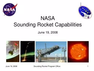
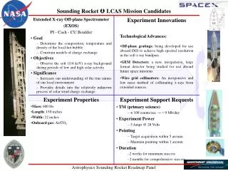
Mission Overview • Objectives / Goals • Measure rocket speed and spin rate • Determine the rocket’s motion and flight path • Design a stable platform to achieve clear images during flight • Successfully retrieve the flight data wirelessly (post-flight) • Obtain basic knowledge and understanding of the design requirements and obstacles in real world applications
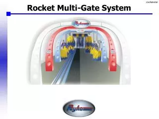
Design Overview: Mechanical Solid Works model of both UW, UM and Augsburg payload system UM Payload Optical Port Stabilized Plate Camera Main Sensor / Processor Board Motor Power Supply Augsburg Payload
Design Overview: Structure • Design and Testing: • Based on last year • Solidworks Analysis • Planned Vibrations Testing Structure deformed under 25g vertical load
Design Overview: Electrical 1.SYS.1 or 1.SYS.2 Compliance
Design Overview: Electrical • Plate Stabilization: • Data is extracted from two peripheral accelerometers • Acceleration data is converted to velocity via the trapezoid rule • The processor then compares current and new rocket velocities • Velocities are converted to steps per second and transmitted to the motor controller
Expected Results • Benefits • Provide Future Rocksat Groups: • Stabilization system for experiments • Accurate data of flight parameters • High quality clear images for future flights • Allow expansion for wireless transmission data post-flight
Testing • Potential Points of Failure • Electrical • Electrical connection breakage during high G’s • Unforeseen code interruption due to interference • Creating own circuit board • Mechanical • Vertical supports buckling • Platter or camera platform malfunction
LessonsLearned • What did we learn from this experience: • Do not procrastinate • Communication is key for a smooth payload integration • Words of wisdom for next year’s groups: • Do not underestimate the size of project • Involve underclassmen • Keep constant communication with other group(s) in canister • Hardest part: • Coordinating presentations and reports for both groups • Programming • Integrating systems together • What would we change: • Less electrical design