Download
1 / 15
150 likes | 302 Views
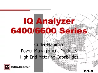
Operating instruction for IQ series laser diode module . Instructions for IQ1C, IQ2C, IQ4C, IQ1A, IQ2A, IQ4A, IQ1H, IQ2H, and IQ4H By Nathan Bran. and power tech.com. Introduction

E N D
Operating instruction for IQ series laser diode module Instructions for IQ1C, IQ2C, IQ4C, IQ1A, IQ2A, IQ4A, IQ1H, IQ2H, and IQ4H By Nathan Bran. and power tech.com
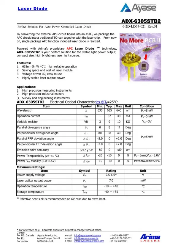
Introduction • The IQ series of laser modules offers the most precise temperature control available from Power Technology, Inc. The IQ series also features quality glass optics and a precision current driver for a wide assortment of laser diodes. • This operating instruction applies to several members of the IQ series: IQ1C, IQ2C, IQ4C, IQ1A, IQ2A, IQ4A, IQ1H, IQ2H and IQ4H. Within the part number, the number 1 represents modules with a laser diode driver, active temperature control, and a simple optical system. The number 2 represents laser modules with the same specifications, with the addition of a more advanced optical system that incorporates a pair of anamorphic prisms for beam circularization.
The number 4 represents laser modules that use a 14-pin butterfly or 14-pin dual-in-line laser package and have a fiber optic output. The letter A represents laser modules with 70MHz analog beam modulation, while the letter H represents laser modules with 100MHz TTL beam modulation. The letter C represents laser modules with CW output. • IQ series laser modules can be configured with a variety of laser diodes at various output powers and operating wavelengths. Products with IR outputs or with output powers above 5mW are not intended for surveying, leveling, and alignment applications. Visible units with output powers below 5mW are----
IQ series laser modules can be configured with a variety of laser diodes at various output powers and operating wavelengths. Products with IR outputs or with output powers above 5mW are not intended for surveying, leveling, and alignment applications. Visible units with output powers below 5mW are CDRH-certified as laser systems.
Installation • Do not mount the laser in a thermal insulating material, such as foam plastic. Heat can have adverse effects on laser diodes. Such effects include decreased output power and large shifts in wavelengths. For best heat dissipation, use a metal mounting fixture such as Power Technology, Inc.’s MB6 mounting bracket. A heat sink is always recommended for operating temperatures above 25°C. • Operating voltages for IQ series modules are 5 to 12VDC, with most diodes operating optimally at 5VDC. However, IQ modules that incorporate certain diodes (e.g., 405nm 5mW) must operate from 6VDC, while others (e.g., 405nm 60mW, 375nm 10mW, 445nm 50mW) must operate from 7VDC.
If the label attached to the laser module reads, ”Complies with 21CFR 1040.10 and 1040.11,” a permanently installed switch at the power source will be required to retain the modules certification as a laser system. This certification is void if the unit is enclosed or otherwise inaccessible, if the labels are modified or removed, or if the system is permanently connected (e.g., soldered) directly to the power source without the required switch. Modifying the laser will void the CDRH certification. If the distance between the laser head and the power source switch exceeds two meters, an emissions indicator must be mounted near the switch. • A 16-pin header connector is present on all IQ series modules and accommodates the DC supply voltage and monitoring connections. Pin one (1) is marked on the back of the unit with a red dot. Connections are listed bellow:
1 2 3 4 5 6 7 8 9 10 11 12 13 14 15 16 PTI 1 2 3 4 5 6 7 8 9 10 11 12 13 14 15 16
Power tech would like to have some more customers. Subscribe • Produced, Incorporated, sales by: Power Tech.(-nology) Power Point created, produced, edited by: Nathan R. Bran.(-ham) A
Me and my editor • p