Download
1 / 21
220 likes | 461 Views
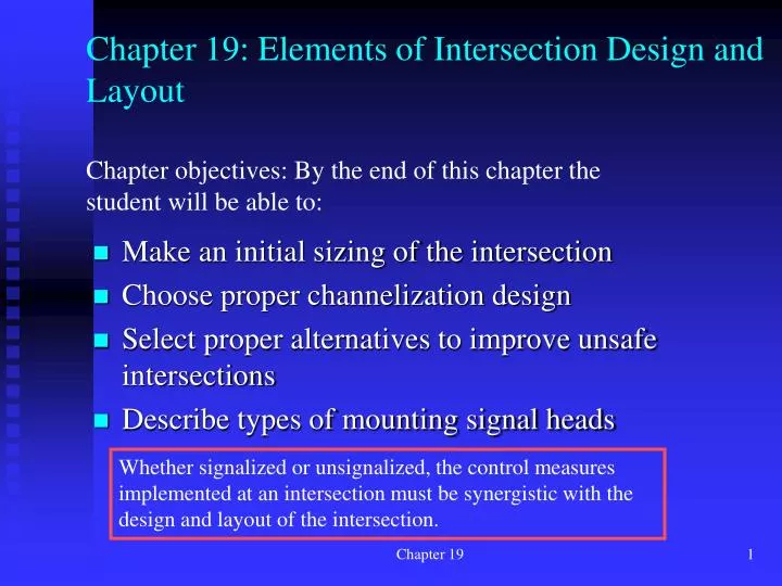
Chapter 19: Elements of Intersection Design and Layout. Chapter objectives: By the end of this chapter the student will be able to:. Make an initial sizing of the intersection Choose proper channelization design Select proper alternatives to improve unsafe intersections

E N D
Chapter 19: Elements of Intersection Design and Layout Chapter objectives: By the end of this chapter the student will be able to: • Make an initial sizing of the intersection • Choose proper channelization design • Select proper alternatives to improve unsafe intersections • Describe types of mounting signal heads Whether signalized or unsignalized, the control measures implemented at an intersection must be synergistic with the design and layout of the intersection. Chapter 19
What’s discussed in this chapter includes techniques for: • Determining the appropriate number and use of lanes at an intersection approach, • Channelization, • Right- and left-turn treatments, • Special safety issues at intersections, • Location of intersection signs and signal displays. Chapter 19
19.1 Intersection Design Objectives and Considerations • To ensure safety for all users, including drivers, passengers, pedestrians, bicyclists, and others • To promote efficient movement of all users (motorists, pedestrians, bicyclists, etc.) Two primary objectives for intersection design: Chapter 19
The elements considered: • Human factors (approach speed, user expectancy, decision and reaction times, etc. • Traffic considerations (appropriate capacity, distribution of vehicle types and turning movements, approach speeds, special treatments for transit vehicles, pedestrians, and bicycles) • Physical elements (abutting properties, traffic movements generated by them, intersection angle, existence and location of traffic control devices, sight distances, specific geometric characteristics) • Economic factors (cost of improvements, effects of improvements on the values of abutting properties, the effect of improvements on energy consumption • Functional intersection area (operational intersection area including deceleration and acceleration zones as well as queuing areas) Chapter 19
19.2 A Basic Starting Point: Sizing the Intersection (how many lanes do we need?) 19.2.1 Unsignalized intersections • STOP or YIELD – see chapter 16 • LT and RT lane considerations for Stop- or Yield-controlled intersections. • Assumptions: • All through vehicles • Capacity 80% of a lane Chapter 19
19.2.2. Signalized intersections (see chapters 17 and 18) • Check LT needs • Determine proper phase sequence • Determine critical movements • Determine cycle length and split effective green time Assumptions: h = 2.6 sec/veh tL = 4 sec/phase Tab 19.3 Sample Prob. Chapter 19
Sample Problem Vc Chapter 19
19.3 Intersection Channelization 19.3.1 General principles • Vehicle paths may be confined so that no more than two paths cross at any one point • The angles at which merging, diverging, or weaving movements occur may be controlled • Pavement area may be reduced, decreasing the tendency to wander and narrowing the area of conflict between vehicle paths • Clear indications of proper vehicle paths may be provided • Predominant movements may be given priority • Areas for pedestrian refuge may be provided • Separate storage lanes may be provided to permit turning vehicles to wait clear of through traffic lanes • Space may be provided for the mounting of traffic control devices in more visible locations • Prohibited turns may be physically controlled • Vehicle speeds may be somewhat reduced Chapter 19
Freedom & Bulldog Chapter 19
19.3.2 Some examples and 13.3.3 Channelizing right turns • Look at the examples shown in pages 545 and 547 and learn what you can do with channelization to provide safer and smoother turns • Make certain a RT bay is not blocked by queued through vehicles. Queue length must be estimated. Otherwise the RT bay will be useless (but you see this example at many locations, e.g., the RT lane on Bulldog WB at Taco Bell; the LT lane on northbound on University Parkway at Brent Brown car dealership Chapter 19
19.4 Special Situations at Intersections 19.4.1 Intersections at skewed angles (Read carefully) Potential realignment Existing Which one is better? Alternative solution using channelization Chapter 19 Realignment of 4-leg odd-angle intersection: Remember two intersections are created.
19.4.2 T-intersections: Opportunities for creativity Layout and phasing Chapter 19
19.4.3 Offset intersections – Problems and solutions Chapter 19
19.4.4 Special treatments for heavy LT movements – Think of advantages and disadvantages of these Chapter 19
RT Lanes Continuous flow intersection LT Lanes LT Lanes Chapter 19 http://www.abmb.com/cfi.html
The Advantages of CFI • Simulations using VISSIM traffic modeling software show that CFI outperforms conventional alternatives dramatically. In case after case, CFI produced extraordinary improvements in levels of service under existing traffic loads and reductions in average intersection delay of 90% or more. • Achieves significantly more capacity than conventional at-grade intersection designs. • Offers substantial savings over grade-separated alternatives while providing equal or better performance. • Can be deployed in one-, two-, three-, and four-legged versions. • Requires little more right-of-way than a conventional at-grade intersection. • Provides clear lines of sight, avoiding the visual barriers created by overpasses. • Helps reduce pollution by reducing congestion. • Requires shorter construction time and less utility relocation. Chapter 19
Diverging Diamond Interchange American Fork Main St. Interchange proposed design. Chapter 19
19.5 Street Hardware for Signalized Intersections • At least one of the two required signal faces for the major movement must be located between 40 and 150 ft of the STOP line, unless the physical design of the intersection prevents it. • All signal faces should be placed within a horizontal 20º angle around the centerline of the intersection approach (including exclusive left- and/or right-turn lanes) Chapter 19
All signal faces should be placed at mounting heights in conformance with MUTCD standards X-axis related to street width Chapter 19
Mast-mounted Post-mounted Chapter 19