Download
1 / 34
520 likes | 2.38k Views
Chapter 18. Shafts and Axles. Dr. A. Aziz Bazoune King Fahd University of Petroleum & Minerals Mechanical Engineering Department. Chapter Outline.

E N D
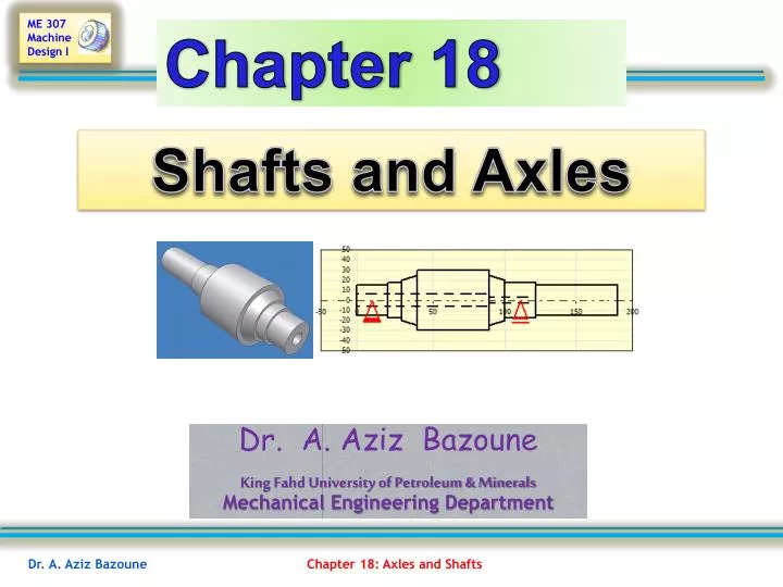
Chapter 18 Shafts and Axles Dr. A. Aziz Bazoune King Fahd University of Petroleum & Minerals Mechanical Engineering Department
Chapter Outline 18-1 Introduction ……….92218-2 Geometric Constraints ……….92718-3 Strength Constraints ……….93318-4 Strength Constraints – Additional Methods ……….940 18-5 Shaft Materials ……….94418-6 Hollow Shafts ……….94418-7 Critical Speeds (Omitted) ……….94518-8 Shaft Design ……….950
Estimating Stress Concentration • The stress analysis process for fatigue is highly dependent on stress concentrations. • Stress concentrations for shoulders and keyways are dependent on size specifications that are not known the first time through the process. • Fortunately, since these elements are usually of standard proportions, it is possible to estimate the stress concentration factors for initial design of the shaft. These stress concentrations will be fine-tuned in successive iterations, once the details are known.
Estimating Stress Concentration • Shoulders for bearing and gear support should match the catalog recommendation for the specific bearing or gear. • A look through bearing catalogs shows that a typical bearing calls for the ratio of D/d to be between 1.2 and 1.5. • For a first approximation, assume D/d =1.5 can be assumed. • Fillet radius at the shoulder needs to be sized to avoid interference with the fillet radius of the mating component. There is a significant variation in typical bearings in the ratio of fillet radius r/d versus bore diameter, with typically ranging from around 0.02 to 0.06.
Estimating Stress Concentration • Figures A-15-8 and A-15-9 show that the stress concentrations for bending and torsion increase significantly in this range. For example, with D/d = 1.5 for bending • In most cases the shear and bending moment diagrams show that bending moments are quite low near the bearings, since the bending moments from the ground reaction forces are small.
Estimating Stress Concentration • In cases where the shoulder at the bearing is found to be critical, the designer should plan to select a bearing with generous fillet radius, or consider providing for a larger fillet radius on the shaft by relieving it into the base of the shoulder as shown in Fig. 7-9a. • This effectively creates ahead • zone in the shoulder area that • does not carry the bending • stresses, as shown by the stress • flow lines. Fig. 7-9a.
Estimating Stress Concentration • A shoulder relief groove as shown in Fig. 7-9b can accomplish a similar purpose. Another option is to cut a large-radius relief groove into the small diameter of the shaft, as shown in Fig. 7-9c. Fig. 7-9b. Fig. 7-9c.
Figure 7-9 Techniques for reducing stress concentration at a shoulder supporting a bearing with a sharp radius. (a) Large radius undercut into the shoulder. (b) Large radius relief groove into the back of the shoulder. (c) Large radius relief groove into the small diameter.
This has the disadvantage of reducing the cross-sectional area, but is often used in cases where it is useful to provide a relief groove before the shoulder to prevent the grinding or turning operation from having to go all the way to the shoulder. • For the standard shoulder fillet, for estimating Kt values for the first iteration, an r/d ratio should be selected so Ktvalues can be obtained. For the worst end of the spectrum, with r/d = 0.02 and D/d = 1.5, Kt values from the stress concentration charts for shoulders indicate 2.7 for bending, 2.2 for torsion, and 3.0 for axial.
Akeyway will produce a stress concentration near a critical point where the load transmitting component is located. The stress concentration in an end-milled keyseat is a function of the ratio of the radius r at the bottom of the groove and the shaft diameter d. For early stages of the design process, it is possible to estimate the stress concentration for keyways regardless of the actual shaft dimensions by assuming a typical ratio of r/d = 0.02. This gives Kt = 2.2 for bending and Kts= 3.0 for torsion, assuming the key is in place.
Akeyway will produce a stress concentration near a critical point where the load transmitting component is located. The stress concentration in an end-milled keyseat is a function of the ratio of the radius r at the bottom of the groove and the shaft diameter d. For early stages of the design process, it is possible to estimate the stress concentration for keyways regardless of the actual shaft dimensions by assuming a typical ratio of r/d = 0.02. This gives Kt = 2.2 for bending and Kts= 3.0 for torsion, assuming the key is in place.
Table 7-1 First iteration estimates for stress concentration factors Kt Warning: These factors are only estimates for use when actual dimensions are not yet determined. Do not use these once actual dimensions are available.
Fatigue Analysis of Shafts The fatigue strength will be determined using: Distortion-Energy-Gerber 2 Distortion-Energy-Elliptic Rotating Shaft under stationary bending and torsional moments
Fatigue Analysis of Shafts SafetyFactor Gerber ASME-Elliptic
Problem 18-10 A geared industrial roll shown in the figure is driven at 300 rev/min by a force F acting on a 3-in-diameter pitch circle as shown. The roll exerts a normal force of 30 lbf/in of roll length on the material being pulled through. The material passes under the roll. The coefficient of friction is 0.40. Develop the moment and shear diagrams for the shaft modeling the roll force as a concentrated force at the center of the roll,
Problem 18-10 We have a design task of identifying bending moment and torsion diagrams which are preliminary to an industrial roller shaft design. Gear Roller
This approach over-estimates the bending moment at C, torque at C but not at A.
Problem 18-11 Using a 1035 hot rolled steel, estimate the necessary diameter at the locations of peak bending moment using a design factor of 2. These are likely to be fillets at both ends of the right hand bearing seat, where the bending moment is slightly less than the local extreme. Estimating the fatigue stress-concentration factor as 2, and using a design factor of 2, what is the approximate necessary diameter of the bearing seat using the DE-elliptic fatigue failure criterion in Problem 18-10?
Problem 18-11 From static Analysis
Hollow Shafts As an example equation 18-21 is modified to take into account the hollow shaft case: where diand do are respectively the inner and outer diameters of the shaft. With this, one can consider that the stress-strength analysis is completed. You have obtained the minimum diameter at the critical section that can withstand the applied loads.
Shaft Design One approach is (See Lab Handbook): Selecting a material (usually steel) Drawing a free body diagram of the shaft Performing static equilibrium analysis and Locating the critical area Performing static stress analysis to find a starting diameter size, d’. Using the value of d’ in calculating the endurance limit (a trial diameter can also be used) Estimating the critical value of the diameter, d, using DE-Gerber or DE-ASME-elliptic methods Repeat step 6 if d different from d’. Building the rest of the shaft by considering the machine parts to be mounted on the shaft (bearings, gears, pulleys, …) Performing deflection analysis Performing Dynamic analysis
Shaft Materials • Shafts are usually made of ductile materials. • Small shafts with diameters less than 3.5 in (90 mm) are usually made of Cold Drawn carbon steel (AISI 1018-1050). • Larger diameter shafts are machined from Hot Rolled steel. • Heat treated steels are also used when higher strengths are necessary.
Shaft N Y Design? find safety Factor, n Find critical diameter, d Y N N Y Shaft rotating? Shaft rotating? Static Analysis Static Analysis Eq. 6-43 or 6-45 Eq. 6-42 or 6-44 Fatigue Analysis Static Analysis Eq. 6-44 or 6-46 d d' Fatigue Analysis n Reversed Y N bending & steady torque? Reversed Y N bending & steady torque? Eq. 18-17 or 18-22 Eq. 18-14 or 18-20 n Eq. 18-16 or 18-21 Eq. 18-13 or 18-19 d N N d. NE. d’ Y d = Critical shaft diameter Complete shaft geometry & perform Deformation analysis
Geometric Constraints • Unlike stress, which is a function of local geometry and load, deflection is a function of the geometry everywhere. Thus, The task of deflection and rigidity analyses can be started only when the entire geometry of the shaft is determined. • However the approach described in section 18-2, which is based on bearing slope constraints as limiting, may be used first assuming a uniform diameter shaft and using equations 18-1 and 18-2 to find the diameters at the bearings.
Shoulders Shoulder Sled runner keyseat Groove Shoulders Profile keyseat Stress Concentrations and Shaft Geometry Shaft shoulders are used to position and provide necessary thrust supports for elements such as bearings, gears, pulleys,… Provisions must be made for torque-transfer elements such as keys, splines, pins The theoretical stress concentration factors for shoulders, grooves and transverse holes can be obtained from appendix [A15+]. Others are Kt = 2.0 for profile key seats Kt = 1.6 for sled runner keyseats
Shaft Geometry To determine the entire geometry of the shaft one has to rely on existing models. Some of these models are given in figures 18-1 through 18-8 of the Textbook. More shaft configurations can be found in the FAG handbooks of the Design of Rolling Bearing Mountings.
Geometric Constraints: Shaft Deflection and Slopes • The transverse deflection of the elastic curve of the shaft can be determined by any one of the methods studied in Chapter 5. • The superposition method, which utilizes Appendix A-9, is recommended. For complex shaft geometry the numerical integration or computer program may be used.
Geometric Constraints: Shaft Deflection and Slopes The slope at ball bearings should be limited at 0.25 deg the slope at roller bearings and long journal bearings should be a lot less. For details on acceptable slopes refer to FAG and SKF catalogs. For machinery shafting, the deflection should be no greater than 0.001 in/ft (0.075 mm/m) of shaft length between bearing supports. For shafts mounting good quality spur gears, the deflection at the gear mesh should not exceed 0.005 in. (0.125 mm) or F/200 (F is the gear face width in inches) and the slope should be limited 0.0286 deg. For shafts mounting good quality bevel gears, the deflection at the gear mesh should not exceed 0.003 in. (0.076 mm).