Download

1 / 36
750 likes | 2.24k Views
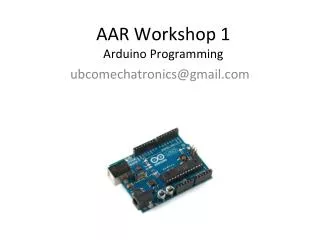
PROGRAMMING WITH ARDUINO. Arduino. An open-source hardware platform based on an Atmel AVR 8-bit microcontroller and a C++ based IDE Over 300000 boards have been manufactured Arduino Due is based on a 32-bit ARM Cortex. Typical Arduino Board. Arduino IDE. Important functions.

E N D
Arduino • An open-source hardware platform based on an Atmel AVR 8-bit microcontroller and a C++ based IDE • Over 300000 boards have been manufactured • Arduino Due is based on a 32-bit ARM Cortex
Important functions • Serial.println(value); • Prints the value to the Serial Monitor on your computer • pinMode(pin, mode); • Configures a digital pin to read (input) or write (output) a digital value • digitalRead(pin); • Reads a digital value (HIGH or LOW) on a pin set for input • digitalWrite(pin, value); • Writes the digital value (HIGH or LOW) to a pin set for output
Using LEDs void setup() { pinMode(77, OUTPUT); //configure pin 77 as output } // blink an LED once void blink1() { digitalWrite(77,HIGH); // turn the LED on delay(500); // wait 500 milliseconds digitalWrite(77,LOW); // turn the LED off delay(500); // wait 500 milliseconds }
Creating infinite loops void loop() //blink a LED repeatedly { digitalWrite(77,HIGH); // turn the LED on delay(500); // wait 500 milliseconds digitalWrite(77,LOW); // turn the LED off delay(500); // wait 500 milliseconds }
Using switches and buttons const int inputPin = 2; // choose the input pin void setup() { pinMode(inputPin, INPUT); // declare pushbutton as input } void loop(){ int val = digitalRead(inputPin); // read input value }
Reading analog inputs and scaling const int potPin = 0; // select the input pin for the potentiometer void loop() { int val; // The value coming from the sensor int percent; // The mapped value val = analogRead(potPin); // read the voltage on the pot (val rangesfrom 0 to 1023) percent = map(val,0,1023,0,100); // percent will range from 0 to 100.
Creating a bar graph using LEDs const int NoLEDs = 8; const int ledPins[] = { 70, 71, 72, 73, 74, 75, 76, 77}; const int analogInPin = 0; // Analog input pin const int wait = 30; const boolean LED_ON = HIGH; const boolean LED_OFF = LOW; int sensorValue = 0; // value read from the sensor int ledLevel = 0; // sensor value converted into LED 'bars' void setup() { for (int i = 0; i < NoLEDs; i++) { pinMode(ledPins[i], OUTPUT); // make all the LED pins outputs } }
Creating a bar graph using LEDs void loop() { sensorValue = analogRead(analogInPin); // read the analog in value ledLevel = map(sensorValue, 0, 1023, 0, NoLEDs); // map to the number of LEDs for (int i = 0; i < NoLEDs; i++) { if (i < ledLevel ) { digitalWrite(ledPins[i], LED_ON); // turn on pins less than the level } else { digitalWrite(ledPins[i], LED_OFF); // turn off pins higher than thelevel: } } }
Measuring Temperature const int inPin = 0; // analog pin void loop() { int value = analogRead(inPin); float millivolts = (value / 1024.0) * 3300; //3.3V analog input float celsius = millivolts / 10; // sensor output is 10mV per degree Celsius delay(1000); // wait for one second }
Reading data from Arduino void setup() { Serial.begin(9600); } void serialtest() { int i; for(i=0; i<10; i++) Serial.println(i); }
Using LCDs #include <LiquidCrystal.h> // include the library code //constants for the number of rows and columns in the LCD const int numRows = 2; const int numCols = 16; // initialize the library with the numbers of the interface pins LiquidCrystal lcd(12, 11, 5, 4, 3, 2); void setup() { lcd.begin(numCols, numRows); lcd.print("hello, world!"); // Print a message to the LCD. }
Using PIR motion sensors const int ledPin = 77; // pin for the LED const int inputPin = 2; // input pin (for the PIR sensor) void setup() { pinMode(ledPin, OUTPUT); // declare LED as output pinMode(inputPin, INPUT); // declare pushbutton as input } void loop(){ int val = digitalRead(inputPin); // read input value if (val == HIGH) // check if the input is HIGH { digitalWrite(ledPin, HIGH); // turn LED on if motion detected delay(500); digitalWrite(ledPin, LOW); // turn LED off } }
Using ultrasonic sensors • The “ping” sound pulse is generated when the pingPin level goes HIGH for two microseconds. • The sensor will then generate a pulse that terminates when the sound returns. • The width of the pulse is proportional to the distance the sound traveled • The speed of sound is 340meters per second, which is 29 microseconds per centimeter. The formula for the distance • of the round trip is: RoundTrip = microseconds / 29
Using ultrasonic sensors const int pingPin = 5; const int ledPin = 77; // pin connected to LED void setup() { Serial.begin(9600); pinMode(ledPin, OUTPUT); } void loop() { int cm = ping(pingPin) ; Serial.println(cm); digitalWrite(ledPin, HIGH); delay(cm * 10 ); // each centimeter adds 10 milliseconds delay digitalWrite(ledPin, LOW); delay( cm * 10); }
Using ultrasonic sensors int ping(int pingPin) { long duration, cm; pinMode(pingPin, OUTPUT); digitalWrite(pingPin, LOW); delayMicroseconds(2); digitalWrite(pingPin, HIGH); delayMicroseconds(5); digitalWrite(pingPin, LOW); pinMode(pingPin, INPUT); duration = pulseIn(pingPin, HIGH); // convert the time into a distance cm = microsecondsToCentimeters(duration); return cm ; } long microsecondsToCentimeters(long microseconds) { // The speed of sound is 340 m/s or 29 microseconds per centimeter. // The ping travels out and back, so to find the distance of the // object we take half of the distance travelled. return microseconds / 29 / 2; }
Audio output tone(speakerPin, frequency, duration); // play the tone delay(duration); //wait for the tone to finish
Example • Write a program that plays an A note (440 Hz) for 1 second when a motion sensor detects motion.
Using Interrupts • On a standard Arduino board, two pins can be used as interrupts: pins 2 and 3. • Theinterrupt is enabled through the following line: • attachInterrupt(interrupt, function, mode) • attachInterrupt(0, doEncoder, FALLING);
Interrupt example int led = 77;volatile int state = LOW;void setup(){ pinMode(led, OUTPUT); attachInterrupt(1, blink, CHANGE);}void loop(){ digitalWrite(led, state);}void blink(){ state = !state;}
ChipKit MAX32 • Microcontroller: PIC32MX795F512L • Flash Memory: 512K • RAM Memory: 128K • Operating Voltage: 3.3V • Operating Frequency: 80Mhz • Typical operating current: 90mA • Input Voltage (recommended): 7V to 15V • Input Voltage (maximum): 20V • I/O Pins: 83 total • Analog Inputs: 16 • Analog input voltage range: 0V to 3.3V • DC Current per pin: +/-18mA • Advanced peripherals: • 10/100 Ethernet MAC • USB 2.0 Full Speed OTG controller • 2 CAN controllers. • External Interrupts: Pin 3 (INT0), Pin 2(INT1), Pin 7 (INT2), Pin 21 (INT3), Pin 20(INT4)
Basic I/O Shield • Features • 128x32 pixel OLED graphic display • I2C temperature sensor • 256Kbit I2C EEPROM • I2C daisy chain connector • 4 push buttons • 4 slide switches • 8 discrete LEDs • 4 open drain FET drivers • Analog potentiometer
Temperature Sensor • A digital temperaturesensor is provided using a Microchip TCN75A2-Wire Serial Temperature Sensor. Thetemperature sensor, IC2, is an I2C device, andis located in the lower right corner of the board. • The TCN75A is rated for an accuracy of +/-1ºCand has selectable resolution from 0.5ºC downto 0.0625ºC. The seven bit device address is‘1001000’. • Digilent provides a library for accessing thetemperature sensor. This library is available onthe Digilent web site and in the third partylibrary repository on github. • Using the temperature sensor with the MAX32 board requires manually connecting the SDA and SCL pins to the basic I/O shield
Configuring Temperature sensor • void config(uint8_t configuration) • Parameters • configuration - Value to be written to config register • This function writes the configuration register with the given value. There are a number of defined • values as described below that can be or’d together to set multiple parameters. For example if one • wished to put the device in one shot mode and use 12 bit resolution the following call could be made. • Config(ONESHOT | RES12) • IOSHIELDTEMP_ONESHOT 0x80 //One Shot mode • IOSHIELDTEMP_RES9 0x00 //9-bit resolution • IOSHIELDTEMP_RES10 0x20 //10-bit resolution • IOSHIELDTEMP_RES11 0x40 //11-bit resolution • IOSHIELDTEMP_RES12 0x60 //12-bit resolution • IOSHIELDTEMP_FAULT1 0x00 //1 fault queue bits • IOSHIELDTEMP_FAULT2 0x08 //2 fault queue bits • IOSHIELDTEMP_FAULT4 0x10 //4 fault queue bits • IOSHIELDTEMP_FAULT6 0x18 //6 fault queue bits • IOSHIELDTEMP_ALERTLOW 0x00 //Alert bit active-low • IOSHIELDTEMP_ALERTHIGH 0x04 //Alert bit active-high • IOSHIELDTEMP_CMPMODE 0x00 ///comparator mode. • IOSHIELDTEMP_INTMODE 0x02 //interrupt mode • IOSHIELDTEMP_STARTUP 0x00 //Shutdown disabled • IOSHIELDTEMP_SHUTDOWN 0x01 //Shutdown enabled • IOSHEIDLTEMP_CONF_DEFAULT //Power up initial configuration
Reading Temperature sensor • float getTemp() • Retrieves the current temp from the temp sensor and converts the returned value into asigned floating point value.
Example void setup(){ IOShieldTemp.config(IOSHIELDTEMP_ONESHOT | IOSHIELDTEMP_RES11 | IOSHIELDTEMP_ALERTHIGH); } void loop() { float temp; int celsius; char sign, msd_char, lsd_char; //Get Temperature in Celsius. temp = IOShieldTemp.getTemp(); }
Potentiometer • A potentiometer is provided on the board • to be used as an analog signal source or • analog control input. The pot is a 10Kohm • trimmer pot connected between the VCC3V3 • supply and ground. The wiper of the pot is • connected to analog input A0. • The pot is read using the analogRead function.
OLED Display • 128x32 pixels • Each individual pixel can only be on (illuminated) or off(not illuminated) • The display is a serial device that is accessed via an SPI interface. • write-only device
Using the OLED display • Initialization • Mode select • Character • Graphic • Drawing
Example void setup() { IOShieldOled.begin(); } void loop() { char toprint; IOShieldOled.clearBuffer(); IOShieldOled.setCursor(0, 0); toprint = ‘A’; IOShield0led.putChar(toprint); }