Download
1 / 24
240 likes | 262 Views
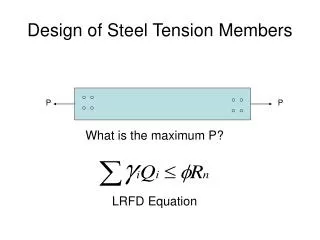
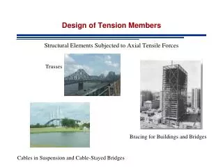
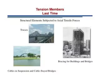
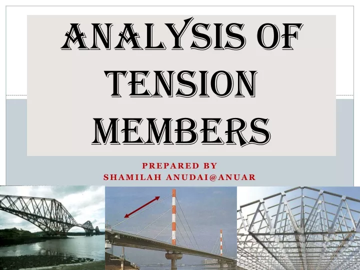
ANALYSIS OF TENSION MEMBERS. PREPARED BY SHAMILAH ANUDAI@ANUAR. INTRODUCTION. When tension in a member is transmitted by bolts, A then equal the net area, An of the member and U is computed as follows :

E N D
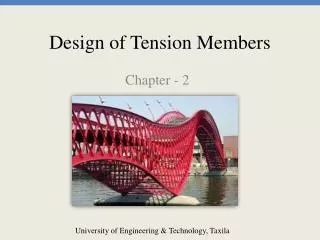
ANALYSIS OF TENSION MEMBERS PREPARED BY SHAMILAH ANUDAI@ANUAR
INTRODUCTION • When tension in a member is transmitted by bolts, A then equal the net area, An of the member and U is computed as follows : • Where U = shear slag coefficient, x = distance from the attached face to the member centroid and L = length of the connection • The length L used in above expression is equal to the distance between the first and the last bolts in the line
(V) • Values of for different shapes (IV)
INTRODUCTION (Cont’d) • The angle shown in (I) is connected at its ends to only one leg • The area effective in resisting tension can be appreciably increased by shortening the width of the unconnected leg and lengthening the width of the connected width as shown in figure I and II • is measured from the plane of the connection to the center of gravity (C.G) or centroid of the whole section.
Determination of U for W section • In order to calculate U for a W section connected by its flange only, it is assumed that the section is split into 2 structural tees. • Then, the value of used will be the distance from the outside edge of the flange to the C.G. of the structural tee as shown in Figure V.
EXAMPLE 1 Determine the tensile design strength of a W10 x 45 with two lines of ¾ in diameter bolts in each flange using A572 Grade 50 steel with Fy = 50 ksi and Fu = 65 ksi and the LRFD specification. There are assumed to be at least three bolts in each line 4-in on center and the bolts are not staggered with respect to each other.
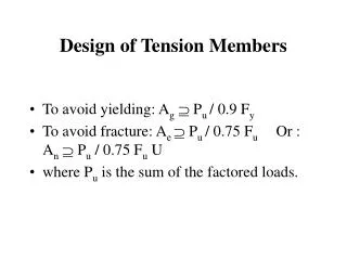
Connecting Elements for Tension Members • Spice and gusset plates are usually used as statically loaded tensile connecting elements. • According to the LFRD Manual, their strength can be determine from ;- - For yielding of connection elements : - For fracture of connection elements : Eq. (a) Eq. (b)
EXAMPLE 2 A tension member W10 x 45 with Fy =50ksi and Fu =65 ksi is assumed to be connected at its ends with two 3/8 x 12-in plates as shown in Figure below. If two lines of 3/4-in bolts are used in each plate, determine the design tensile force which the plates can transfer and yield.
BLOCK SHEAR • The design strength of a tension member is not always controlled by or by the strength of the bolts or weld s with which the member is connected. • It may instead be controlled by its block shear strength as will be described.
Failure due to Block Shear - The failure of a member may occur along a path involving tension on one plane and shear on a perpendicular plane as shown in Figure below. - In this figure, several possible block shear failures are shown - For these situations, it is possible for a “block” to tear out
Failure due to Block Shear (cont’d) - When a tensile load applied to a particular connection is increased, the fracture strength of the weaker plane will be approached - That plane will not fall because it is restrained by the stronger plane - The load can be increased until the fracture strength of the stronger plane is reached - During this time, the weaker plane is in yielding
Failure due to Block Shear (cont’d) - The total strength of the connection equals the fracture strength of the stronger plane plus the yield strength of the weaker plane. - However, it is not realistic to add the fracture strength of one plane to the fracture strength of the plane to determine the block shear capacity of a particular member.
Failure due to Block Shear (cont’d) - The member shown in Figure below has a larger shear area and a small tensile area. - Therefore, the primary resistance to a block shear failure is shearing and not tensile - The LFRD Specification states that it is logical to assume that when shear fracture occurs on this large shear-resisting area, the small tensile area has yielded
LFRD Specification on Block Shear Eq. (c) Eq. (d)
EXAMPLE 3 The A572 Grade 50 (Fu =65 ksi) tension member shown is connected with three ¾-in bolts. Determine the block shearing strength of the member and its tensile strength
Two types of load cases on a bolted connection can be discriminated. One where the load is in the axial direction of the bolts and the other where the load transfer is perpendicular to the bolt axis. In this Lecture these two types are referred to as: I Bolted connections loaded in tension II Bolted connections loaded in shear. • An example of the first type is a bolted flange connection as shown in Figure 1. An example of the second type is a bolted cover plate connection in a flange of a beam section or a simple strip, see Figure 2. In the latter case the load is transferred by shear either in the bolts (for non preloaded bolts) or at the plate surfaces (for preloaded bolts).
THANK YOU VERY MUCH FOR YOUR ATTENTION