Download
1 / 61
640 likes | 848 Views
Embedded System Spring, 2011 Lecture 5: The PIC Microcontrollers Eng. Wazen M. Shbair. Today’s Lecture. Using instruction with the default access bank. PIC Status Register. Introduction to PIC Assembly Language. Using instruction with the default access bank.

E N D
Embedded SystemSpring, 2011Lecture 5: The PIC MicrocontrollersEng. Wazen M. Shbair
Today’s Lecture • Using instruction with the default access bank. • PIC Status Register. • Introduction to PIC Assembly Language IUG- Embedded System
Using instruction with the default access bank • We need instruction to access other locations in the file register for ALU and other operations. • MOVWF • COMF • DECF • MOVF • MOVFF
Access bank in the PIC18 • It is 256-Byte bank. • Divided into equal two discontinuous sections (each 128 B). • GP RAM, from 0 to 7FH • SFR, from F80H to FFFH
MOVWF instruction WREG • F indicates for a file register MOVWF Address • It tells the CPU to copy the source register, WREG, to a destination in the file register. • A location in the SPR • A location in GP RAM 1-6
Example 2-1 WRFG 99 85 3F 63 12 MOVLW 99H MOVWF 12H MOVLW 85H MOVWF 13H MOVLW 3FH MOVWF 14H MOVLW 63H MOVWF 15H MOVLW 12H MOVWF 16H
Note We cannot move literal values directly into the general purpose RAM location in the PIC18. They must be moved there via WREG. 1-8
ADDWF • Adds together the content of WREG and a file register location ADDWF File Reg. Address, D • The result will be placed in either the WREG or in the file register location • D indicates the destination bit • If D=0 or (D=w) • The result will be placed in the WREG • If D=1 or (D=f) • The result will be placed in the file register 1-9
Example 2-2 0 22 State the content of file register location and WREG after the following program MOVLW 0 MOVWF 12H MOVLW 22H ADDWF 12H, F ADDWF 12H, F ADDWF 12H, F ADDWF 12H, F
Example 2-3 0 22 44 66 88 State the content of file register location and WREG after the following program MOVLW 0 MOVWF 12H MOVLW 22H ADDWF 12H, F ADDWF 12H, W ADDWF 12H, W ADDWF 12H, W 1-11
COMF instruction COMF File Reg. Address, D It tells the CPU to complement the content of fileReg and places the results in WREG or in fileReg. 1-13
Example 2-4 55 Write a simple program to toggle the SFR of Port B continuously forever. Solution MOVLW 55H MOVWF PORTB B1 COMF PORTB, F GOTO B1 1-14
DECF instruction 3 DECF File Reg. Address, D • It tells the CPU to decrement the content of fileReg and places the results in WREG or in fileReg. • Example: • MOVLW 3 • MOVWF 12H • DECF 12H, F • DECF 12H, F • DECF 12H, F 1-15
DECF instruction 3 2 1 0 DECF File Reg. Address, D • It tells the CPU to decrement the content of fileReg and places the results in WREG or in fileReg. • Example: • MOVLW 3 • MOVWF 12H • DECF 12H, w • DECF 12H, w • DECF 12H, w
MOVF instruction MOVF File Reg. Address, D • It is intended to perform MOVFW • MOVFW isn’t existed • If D=0 • Copies the content of fileReg (from I/O pin) to WREG • If D=1 • The content of the fileReg is copied to itself. 1-17
MOVF instruction WREG MOVF File Reg. Address, 0
Example 2-5 XX Write a simple program to get data from the SFRs of Port B and send it the SFRs of PORT C continuously. Solution AGAIN MOVF PORTB, W MOVWF PORTC GOTO AGAIN
Example 2-6 55 5A Write a simple program to get data from the SFRs of Port B Add the value 5 to it and send it the SFRs of PORT C Solution MOVF PORTB,W ADDLW 05H MOVWF PORTC
MOVFF instruction It copies data from one location in FileReg to another location in FileReg. MOVFF Source FileReg, destination FileReg
Example 2-7 XX Write a simple program to get data from the SFRs of Port B and send it the SFRs of PORT C continuously. Solution AGAIN MOVFF PORTB, PORTC GOTO AGAIN
PIC Status Register • To indicate arithmetic conditions • It is a 8-bit register • Five bits are used • D0: C Carry Flag • D1: DC Digital Carry Flag • D2: Z Zero Flag • D3: OV Overflow Flag • D4: N Negative Flag
Example 2-8 • Show the status of the C, DC, Z flags after the following addition instruction MOVLW 38H ADDLW 2FH • Solution • 38H + 2FH = 67H WREG=67H C=0 DC=1 Z=0
Example 2-9 • Show the status of the C, DC, Z flags after the following addition instruction MOVLW 9CH ADDLW 64H • Solution • 9CH + 64H = 100H WREG= 00H C=1 DC=1 Z=1
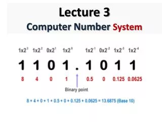
PIC Data Format and Directives • There is one data type • 8 bits • It is the job of the programmer to break down data larger 8 bits • Data type can be positive or negative • Data format are • Hex (default in PIC) 12 or 0x12 or H'12' or 12H • Binary B'00010010' • Decimal .12 or D'12' • ASCII A'c' or a'c' 1-29
Assembler Directives • The Instruction tell the CPU what to do , while Directives give direction to assembler • Directives : EQU,SET, ORG (Origin), END, LIST • EQU (equate) • It is used to define a constant value of a fixed address. • It associates a constant number with a data or an address label so that when the label appears in the program , its constant will be substituted for the label .
Assembler Directives • SET • Its used to define a constant value or a fixed, it’s the identical to EQU , but the SET may de reassigned later. • ORG (origin) • It is used to indicate the beginning of the address. • END • This indicates to assembler the end of the source (asm)file.
Assembler Directives • LIST • It indicate to the assembler the specific PIC chip for which the program should be assembled
Rules for labels in Assembly Language • Unique name • Alphabetic letters • Upper, lower, digits (0-9),special char. (? . @_ $) • The first letter must be Alphabetic letters • Not a reserved word 1-33
Introduction to PIC Assembly Language • Difficult for us to deal with the machine code ( 0s and 1s) • Assembly Language provide • Mnemonic: codes and abbreviations that are easy to remember • Faster programming and less prone error • LLL (why?) • Programmer must know all Reg. …etc. • Assembler is used to translate the assembly code into machine code (object code) 1-35
Structure of Assembly Language • Series of lines • Instruction • Directives • Consists of four field [label] mnemonic [operands] [;commands] • Label: refer to line by code (certain length) • Mnemonic and operands are task that should be executed. • Directive don’t generate any machine code and used by assembler 1-36
Sample of Assembly Language Program SUM EQU 10H ;RAM loc 10H fro SUM ORG 0H; start at address 0 MOVLW 25H ; WREG = 25 ADDLW 0x34 ;add 34H to WREG=59H ADDLW 11H ;add 11H to WREG=6AH ADDLW D’18’ ; W = W+12H=7CH ADDLW 1CH ; W = W+1CH=98H ADDLW b’00000110’ ; W = W+6H=9EH MOVWF SUM ;save the result in SUM location HERE GOTO HERE ;stay here forever END ; end of asm source file
Assembling and Linking A PIC Program Figure 2-8. Steps to Create a Program
List File 1-39
The Program Counter and Program ROM Space in the PIC • Program Counter (PC) is used by the CPU to point to the address of the next instruction to be executed • The wider the program counter, more the memory locations can be accessed • PIC16 has 14 bits (8K) • PIC18 has 21 bits (2M) • 8051 has 16 bits (64K) 1-40
Example 2-11 Find the ROM Memory Address of each of the following PIC chips: PIC18F2220 PIC18F2410 PIC18F458
Powering UP • At what address does the CPU wake up when power applied? • The uC wakes up at memory address 0000 • The PC has the value 0000 • ORG directive put the address of the first op code at the memory location 0000
Program Memory All instructions are 2Byte except the GOTO, which has 4-Byte
Program ROM Width for the PIC18 • Byte addressable: each location holds only one byte • CPU with 8-Bit will fetch one byte a time • Increasing the data bus will bring more information • Solution: Data bus between CPU and ROM can be similar to traffic lanes on the highway • The wide of Data path is 16 bit • Increase the processing power • Match the PIC18 instruction single cycle
Little endian VS big endian war The low byte goes to the low memory location The high byte goes to the high memory location Intel uP and many uCs use little endian