Download
1 / 19
620 likes | 1.49k Views
Concrete Box Culverts (CBC). Bar lists and estimates from standard design sheets. CBC. Mostly used as drainage structures Used instead of multi-plate culverts or bridges Can be cast-in-place (CIP) or precast. http://www.scurlockindustries.com/boxclvrt.html.

E N D
Concrete Box Culverts (CBC) Bar lists and estimates from standard design sheets
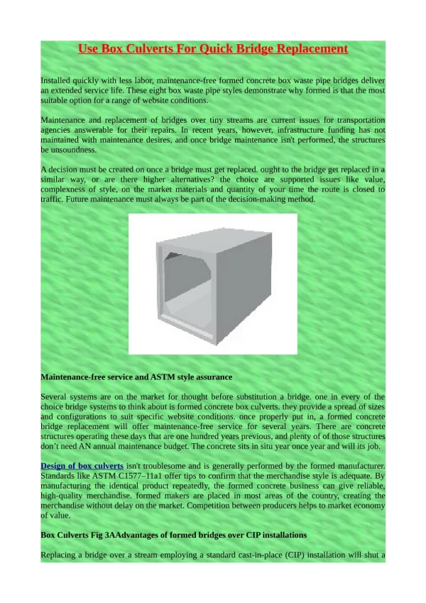
CBC • Mostly used as drainage structures • Used instead of multi-plate culverts or bridges • Can be cast-in-place (CIP) or precast http://www.scurlockindustries.com/boxclvrt.html http://www.metwashairports.com/dulles/1522.htm
Open (3-sided) or Closed (4-sided) • Rock or Precast Concrete Footings-open box (minimizes environmental impact) • Earth or Granular Soil-Closed box (fish baffles can be added) http://www.shawpipe.com/box_culvert.aspx http://www.hansonsilo.com/images/box-culvert-install.jpg
Other (wingwalls, cutoffs, curved..) http://www.shawpipe.com/box_culvert.aspx
Standard Design Sheets-CBC • Section A-A, 1 (6x3 to 9x9) • Type I bar ties walls & slabs together (2 pieces) • Section A-A,2 (10x5 to 17x8) • Type II bars tie walls and slabs together (4 pieces) • Section A-A, 3 (10x9 to 20x20) • Double row of bars in walls. Includes Type VII and type VIII bars • Note: Not for design!!!! Handouts are rescinded standard sheets given solely for education purposes (looking at details and deriving bar lists).
Steel Bars-Miscellaneous • Minimum cover on non-prestressed steel (ACI 318) • Cast against or permanently exposed to earth 3” • Exposed to earth or weather • #5 and smaller 1-1/2” • #6 and larger 2” • Minimum cover is also shown on Handouts. Note says assume 2” unless otherwise shown, but we’ll assume 3” for end cover
Steel BarsSpacing vs # of Bars • (Dimension minus cover) divided by (minimum spacing) +1 • 2 ft @ 6” spacing would require 5 bars • 24”-4”=20/6=4+1=5 Note: Otherwise spacing would be more than 6”
General Design Steps Using Standard Design Sheets • Determine flow (hydrology) • Determine span x height (hydraulics) • Determine skew • Determine height of fill (top of roadway to top of top slab of culvert) • Determine the following: • Required wall thickness • Slab thickness • Bar Reinforcement • Size and Spacing of Steel Bars
CBC Example • Height of Fill (HF) 5’ • Span (S) 15’ • Height (H) 8’ • Length (L) 40’ • Section A-A,2
CBC Example Determine: • Top Slab Thickness (t)=12” • Wall Thickness (w)=12” • Bottom Slab Thickness (t+2”)=14” • Dimension “a”=5’-7” • Dimension “b”=3’-7”
CBC Example Determine bar size and spacing: • Type I #5@18” (gave name to bar) • Type II #6@6” • Type III #7@6” • Type IV #5@12” • Type V #5@9” • Type VI #5@18”
CBC Example Type I bars (#5 @ 18”) are straight bars which run the length of the barrel and are located in the walls: • Determine Dimension: 8’*12”/ft=96”-8”(bottom haunch)-4”(top haunch )-4”(cover)=80” • Determine # of Bars: 80”/18”=5+1=6 bars per wall *2 walls =12 bars • Determine bar length: 40’-6” (end cover)=39’-6” Discussion on length & splices
Repeat for other bars • Type II bars are curved bars which tie slabs and walls together (dimensions are given in standard drawings) • Type III bars are straight bars which run the width of the span and are located in the top and bottom slabs. They overlap the walls • Type IV bars are straight bars which run the width of the span (don’t overlap walls) and are located in the top and bottom slabs
Repeat for other bars • Type V bars are straight bars which run the length of the barrel and are located in the top and bottom slabs near the type IV bars • Type VI bars are straight bars which run the length of the barrel and are located in the top and bottom slabs near the type III bars)
Determine Concrete Volume • Top Slab • Top Haunches • Side Walls • Bottom Slabs • Bottom Haunches • Volume=82 CY • Don’t subtract steel volume • Discuss staging
Bar List, Detailed Drawing, Estimate • Complete the bar list (#’s of steel) • Provide a detailed drawing specific to your project • Estimate