Download
1 / 18
180 likes | 291 Views
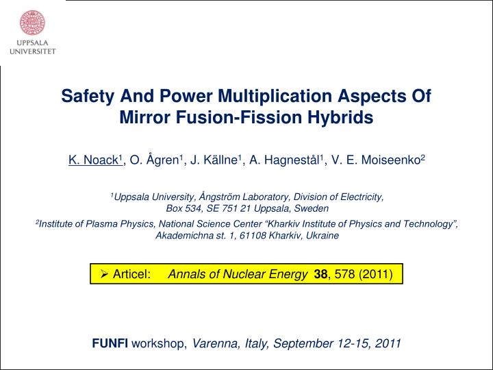
Safety And Power Multiplication Aspects Of Mirror Fusion-Fission Hybrids. K. Noack 1 , O. Ågren 1 , J. Källne 1 , A. Hagnestål 1 , V. E. Moiseenko 2 1 Uppsala University, Ångström Laboratory, Division of Electricity, Box 534, SE 751 21 Uppsala, Sweden

E N D
Safety And Power Multiplication Aspects Of Mirror Fusion-Fission Hybrids K. Noack1, O. Ågren1, J. Källne1, A. Hagnestål1, V. E. Moiseenko2 1Uppsala University, Ångström Laboratory, Division of Electricity, Box 534, SE 751 21 Uppsala, Sweden 2Institute of Plasma Physics, National Science Center “Kharkiv Institute of Physics and Technology”, Akademichna st. 1, 61108 Kharkiv, Ukraine • Articel:Annals of Nuclear Energy 38, 578 (2011) FUNFI workshop, Varenna, Italy, September 12-15, 2011
2/17 • CONTENT • PresentNeutronic Model • SafetyConsiderations • DiscussionandConclusions
1. Present Neutronic Model New component: Reactivity modulator (RM) 3/17 Modified radial structure: TABLE 1. Two hybrid options: A B keff 0.95 0.97 Core thickness (cm) 21.8 22.8 Fission power (GW) 3 1.5 Fusion power (MW) 35-75 11-20 LBE-coolingloop • T-breeding • Thickness • decreased • 20 wt% of • Li-6 • New component: Shield • (60:40) vol% steel&water • Steel with 1.75 wt% Bnat
1. Present Neutronic Model 4/17 Standard axial dependenceoftheneutronsource: : Length of the core = 25 m !
1. Present Neutronic Model 5/17 Reactivityeffectofthe „Reactivitymodulator“ (RM): # Calculation model: • 2 B4C-annuli at the outer core surface at both ends • Thickness = 1 cm, height = 2.5 m • Boron is 90% enriched in 10B ~4000 pcm : Reactivity range = 4000 pcm (10-5)
1. Present Neutronic Model 6/17 Disadvantage & Advantages: • Disadvantage: • Reactor technology has no experience with such long systems. • Advantages: • Highly efficient utilization of the neutron source. • First wall problem is considerably mitigated. • The shielding of the magnetic coils is a fission shielding problem. • The vertical installation could enable natural circulation of the LBE-coolant. See talk O12 of H. Anglart, this workshop. • The long system implies a small leakage and hence a relatively small effect of the thermo-structural expansion. • Low average fission power density of 76 W/cm3 and low average linear pin power of 80 W/cm. • Low radial peaking factor of 1.15 and of 1.30 over the whole core.
2. Safety Considerations PAF Fission power Fusion power *appr Meff • : Threepossibilitiestocontrolthefission power: • Pfus (fusiondriver) • *appr (fusiondriver) • Meff (fissionblanket) PAF Reactivity feedback effects! 7/17 Steady-state power amplification: • Demand: The generation of the fission power must be manageable in any case to prevent the system from damage! • : The blanket must remain sub-critical in any case!
2. Safety Considerations 8/17 Temperaturefeedbackeffectsatstart-up & switch-off: # Calculation model: • Fuel 400 K 1100 K • LBE, structure 400 K 900 K EffectΔkeff /(keff·ΔT) (10-61/K)Δkeff(pcm) Doppler effect of the fuel -1.05 30% ▬73 LBE-coolant density effect -7.4 5% ▬350 Axial core expansion ~ 0 0 Radial expansion of fuel pins 0.4 (from Ref. 12*)19 Radial core expansion -6.8 (from Ref. 12)▬320 (?) *[12] W. M. Stacey, NuclearReactorPhysics, 2004. Data givenfor a Na-cooled FR withoxidefuel. : Expected maximal total temperature effect for start-up/switch-off (or „loss of plasma“): ~ ▬/+800 pcm
2. Safety Considerations 9/17 Coolantvoideffects− Voided radial areaswithinthecore: # Calculation model: LBE-voided radial core areas (cm) 1 [115 < r < 122] 2 [113 < r < 124] 3 [111 < r < 126] 4 entire core 5 buffer&core&expansion zone ~1445 pcm 3% : Expected maximal reactivity effect by radial LBE-voiding: ~ +1500 pcm
2. Safety Considerations 10/17 Coolantvoideffects− Loss of LBE-coolant: # Calculation model: • vertically installed hybrid • united volume of buffer, core, exp. zone • different LBE-levels : Loss ofthe LBE-coolantresults in a negativereactivityeffect!
2. Safety Considerations 11/17 Reactivityeffectsofwater in thecoolantloopand in thevacuumchamber: Cases: 1 – H2O within the core 2 – H2O within core, buffer, exp. zone 3 – H2O within buffer, exp. zone 4 – H2O within the vacuum chamber : • Case 1 must beexcludedby design! • All theother „watereffects“ are negative.
2. Safety Considerations 12/17 *-Effectofthe axial distributionoftheneutronsource: Standard axial dependence of the neutron source # Calculation model: Deformations of the axial dependence. Deformation of the n-Source Ratio of fission heatings (def./stand.) Peak height reduced by factor 2 1.03 Source length compressed to 20 m 1.13 Full intensity concentrated at z=0 1.42
13/17 2. Safety Considerations Axial dependenceofthespecificfissionheating: hfis(z)= Fission heating per source neutron emitted at z hfis = 1513 (MeV)
3. Discussion and Conclusions 14/17 Withregardtotheblanket (A – keff=0.95, B – keff=0.97): • Response to changes of Pfus. • • To reduce thermal shocks the Pfisshould respond gradually. • # In this respect, option B is not worse than A! • Response to inadvertant insertion of (+)-reactivity. • • Worst case: • „Inflow of cold LBE“ + „Ejection of the inserted RM“ • +800 pcm Restriction: ≤ ~1000 pcm • # Then, even B is in deep sub-criticality! • Responses to start-up and switch-off at the beginning of the cycle. • • Start-up (▬800 pcm): • Withdrawal of the RM to meet the nominal criticality in the operation state. • • Switch-off (+800 pcm): • Insertion of the RM to fulfill keff ≤ 0.95 (0.97). • # No safety relevant disadvantage of option B compared to A!
3. Discussion and Conclusions 15/17 Withregardtotheblanket (A – keff=0.95, B – keff=0.97): • Response to „unprotected“ transients. • • Incidence: Driver cannot be shut off on demand. • T- increase insertion of (▬)-reactivity • T-increase is slowed down. • # In this respect, option B is more advantageous than A! Further reduction of the PAF by completely inserting the RM. • # In this respect, option B is more advantageous than A! • Our position: • The shut-off of the driver definitely takes place after a minimal delay! Quantitative estimates of possible core damage need dynamic calculations!
3. Discussion and Conclusions 16/17 Withregardtotheblanket (A – keff=0.95, B – keff=0.97): Response to filling the LBE-coolant loop with water: • Incidence: For example, intended misuse. Negative effects, provided that buffer, core and exp. zone form a united volume! # No safety relevant difference between both hybrid options! • Response to coolant void effects. • • Loss of coolant: negative effect. • • Voided areas within the core: <+1500 pcm • +cooling down the blanket + 800 pcm • • The RM could be used to compensate reactivity. • # Both hybrid options remain sub-critical! Comparisonofthe hybrid options A and B: The studyrevealedthatoption B does not exhibit substantial disadvantageswithregardtosafety! < 2300 pcm
3. Discussion and Conclusions 17/17 Withregardtothemirrordriver: Minimal value as low as possible <Pfus<definite maximal value. The driver must be equipped with several redundant, quick shut-off techniques. Pfusshould be supplied gradually tunable and stable. If Pfusis fluctuating, the frequencies should be clearly above 10 Hz. The probability of plasma collapses must be minimal. The neutron source should have the axial peaks at stable positions. In case of fluctuations, the frequency range should be clearly above 10 Hz.