Download
1 / 34
340 likes | 345 Views
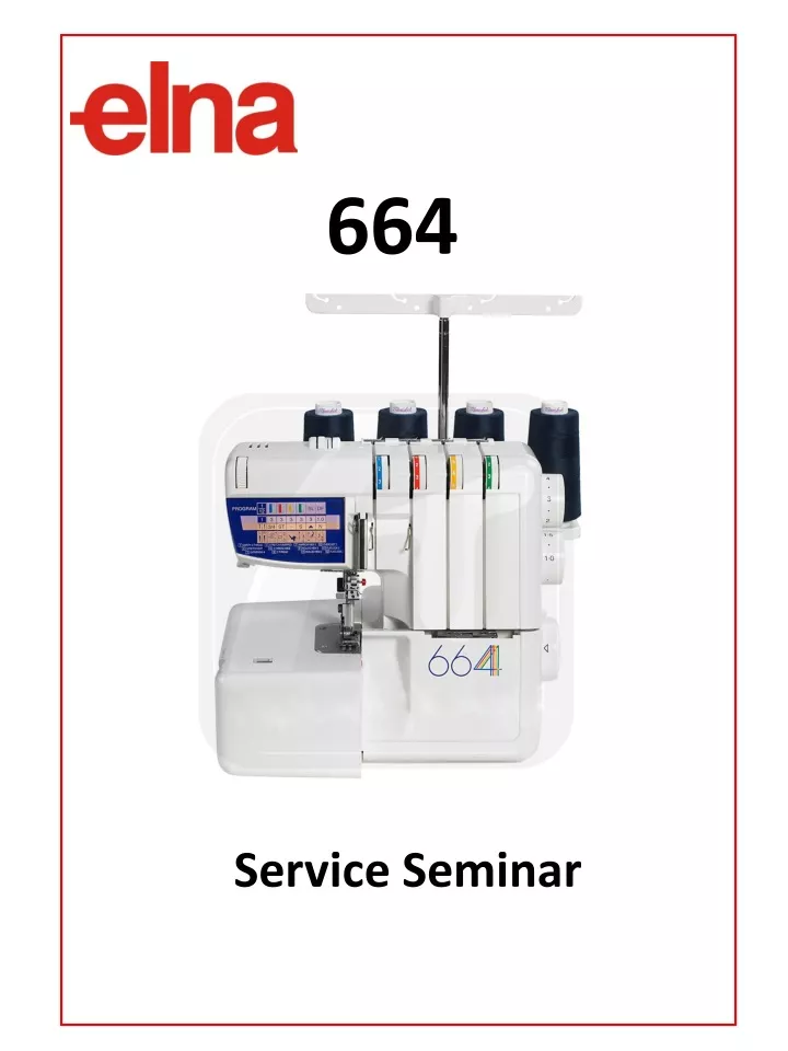
664. Service Seminar. Removing the Face Plate. 1. Turn the sewing machine toward the back and remove the screw. 2. Remove the second screw and remove the face plate. 1. Removing the Belt Cover. 2. Using a flat-head screwdriver, carefully pop off the 2 dials.

E N D
664 Service Seminar
Removing the Face Plate 1. Turn the sewing machine toward the back and remove the screw. 2. Remove the second screw and remove the face plate. 1
Removing the Belt Cover 2. Using a flat-head screwdriver, carefully pop off the 2 dials. 1. Turn the machine tzoward the back and loosen the screw. 3. Lay the machine on it’s back and remove the phillip’s head screw on the bottom cover that holds the belt cover in place. 4. While pushing in on the back of the belt cover, pull out from the rear and remove the cover. 2
Removing the Top Cover 1. Turn the sewing machine toward the back and loosen the 2 screws that hold the top tension cover to the machine. 2. With the 2 screws loosened, lift up on the back of the top cover and remove it completely. 3
Removing the Front Cover 1. With the machine on it’s back, remove the 2 screws that hold the looper door to the machine. 2. While looking in from the back of the front cover by the light bulb, remove this phillips screw that holds the cover to the machine. 3. Remove the screw that holds the right-side of the front cover to the machine. 4
4. Loosen the screw directly above the handwheel. 4. Remove the last 2 screws that hold the front cover to the machine. 5. Bring the upper looper to its lowest position and remove the front cover. 5
Removing the Side Cover 1. Loosen (do not remove) the 2 screws. 2. Remove the side cover. 7
Removing the Base Unit 1. Lay the machine on its back. Remove the 2 screws and the cushions. 2. Remove the 3 silver screws. DO NOT REMOVE THE CUSHIONS. Remove the base unit. 8
Preparation For Service 1. Remove the screw and the entire presser foot 2. Raise the needle bar to its highest point. Remove the left needle. If the right needle is old or damaged, replace it with a new needle. 3. Use a 7mm nut driver or screwdriver to loosen and remove the hexagon bolt. Remove the upper knife. 9
Adjusting the Needle Bar Height 1. Push and hold the metal knob to the right and pull the chaining finger towards you to the R position. Raise the upper looper to its highest position. Loosen the screw inside the top of the upper looper shaft (2.0mm) and pull out the upper looper to the left. 2. Raise the needle bar to its highest position. Place the serger step gauge (part #787G05) on the needle plate, as shown. The tip of the needle should be even with the first step of the gauge or slightly above it. According to factory specifications, the tip of the needle should be 11.6 to 12.2mm above the surface of the needle plate. 3. If an adjustment is needed, loosen the 2.0mm hexagon screw and raise or lower the needle bar. Do not rotate the needle bar while adjusting the height. Tighten the screw. 10
Adjusting the Lower Looper Height 1. Remove the needle plate. 2. Turn the handwheel towards you to bring the lower looper to its most right position. Remove the screw and the lower looper Shoulders 3. Inspect the lower looper drive arm. Make sure that the 2 shoulders are not broken. If either shoulder is damaged or broken, replace the entire lower looper drive arm. 11
4. Inspect the lower looper and replace it, if necessary. Reinstall the lower looper and temporarily tighten the screw. 5. Adjust the height of the lower looper by loosening the screw and moving the looper up and down. Adjust the looper so the slot in the looper is completely covered by the screw. Then firmly tighten the screw. (Do not over tighten the screw) 12
Adjusting Lower Looper Timing and Clearance 1. Locate the needle guard screws. The top 2 screws (2.5mm hexagon) hold the front needle guard. The bottom 2 screws hold the rear needle guard. 2. Loosen the front needle guard by loosening the top 2 hexagon screws. Loosen the screws only enough to enable the needle guard to move. 13
3. Turn the handwheel to bring the needle bar to its lowest position. Place the gauge clamp (part #787G02) on the needle bar as shown. Insert and hold the thickness gauge (part #787G03) above the gauge clamp. Thickness Gauge Clamp Gauge 4. Raise the clamp until clamp and thickness gauge stop. Tighten the screw. 14
5. Remove the thickness gauge. Turn the handwheel toward you to raise the needle bar until it stops. 6. At this point, the tip of the lower looper should be even with the left edge of the needle. 15
7. In order to adjust the lower looper timing and clearance, locate the hexagon bolt (7mm) at the back of the lower looper drive arm. 8. Carefully loosen the hexagon bolt, using a 7mm open-end wrench or a hexagon driver. Loosen it only until you are able to move the lower looper drive arm and it will stay in the position where you set it. Adjust the lower looper timing, but do not tighten the hexagon bolt yet. 9. Move the lower looper to the right slightly until the tip of the lower looper is behind the needle. 16
10. Check the clearance between the lower looper and the needle. The clearance should be .05mm. Use a small screwdriver to push against the needle from the front. The needle should move very slightly. 11. If an adjustment is needed, move the lower looper drive arm in or out until the clearance is .05mm. 12. Tighten the hexagon bolt. To prevent breaking the lower looper drive arm, do not over tighten the bolt. Remove the gauge clamp. 17
Front Needle Guard Clearance 1. Bring the tip of the lower looper behind the needle. Lightly push the front needle guard against the needle until there is no clearance between the needle and lower looper. 2. Tighten the 2 front needle guard hexagon screws. Using the handwheel, move the lower looper back and forth behind the needle. If you hear a loud scraping sound, readjust the front needle guard clearance. A very light rubbing sound is normal. 18
Upper Looper Timing 1. Raise the upper looper shaft to its highest position. Inspect and reinstall the upper looper so that the looper is in front of the needle and resting lightly against the needle. Temporarily tighten the screw inside the upper looper shaft (2.0mm hexagon). 2. Bring the upper looper shaft to its lowest position. Check the clearance between the upper looper shank and the upper looper shaft guide. Use the tip of the serger step gauge to measure this clearance. 3. If an adjustment is needed, loosen the two screws (2.5mm hexagon). 19
Upper Looper Position 1. Raise the upper looper to its highest point. Use the serger step gauge for this adjustment. 2. Place the first step of the gauge lightly against the needle. The second step of the gauge should be centered in the eye of the upper looper. 3. To make an adjustment, loosen the 2.0mm hexagon screw inside the upper looper shaft. Move the upper looper to the left or right, then temporarily tighten the screw. 20
Upper and Lower Looper Timing 1. Bring the upper looper to its lowest position, than raise it until the tip of the looper is even with the bottom edge of the lower looper Sample #1 Sample #2 Wrong 2. The tip of the upper looper should be between .2 to 1.2 mm to the left of the eye of the lower looper. • 3. If an adjustment is needed, loosen the 2 hexagon screws (2.0mm) on the upper looper drive cam and turn the cam: • Away from you if the loopers look like sample #1. • 2. Toward you if the loopers look like sample #2. 21
Upper Looper Clearance 1. Turn the handwheel to bring the upper looper behind the lower looper as shown. 2. The clearance between the upper looper and lower looper should be as zero as possible but no more than 0.2mm, without the loopers hitting each other as they pass. 3. To adjust the clearance, loosen the screw inside the upper looper shaft (2.0mm) and rotate the upper looper forward or backward. Then firmly tighten the screw. 22
Knife Position 1. Remove the two silver screws and remove the looper cover guide. Reinstall the needle plate. 2. The top edge of the lower knife should be level with the surface of the needle plate. The lower knife is replaced by removing the 2 screws. 3. To adjust the lower knife height, first loosen the silver screw located on the lower knife mounting plate. 23
4. Also locate the eccentric shaft. Insert a flat screwdriver to the eccentric shaft and a Phillips screwdriver to the silver screw. While holding the flat screwdriver to the eccentric shaft loosen the silver screw. Rotate the shaft until the top edge of the upper knife is level with the surface of the needle plate. Eccentric shaft 5. Tighten the silver screw by the right side of the lower knife supporting plate making sure that the eccentric shaft does not rotate (use a flat driver as show). 6. Install the upper knife with a 7mm hexagon bolt. 24
7. Turn the handwheel toward you to bring the upper knife to its lowest position. 8. The front lower corner of the upper knife should be 0.8 to 1.5mm below the top edge of the lower knife. To make this adjustment, loosen the hexagon bolt and move the upper knife up or down. Tighten the hexagon bolt. 9. Reinstall the looper cover guide. Inset and tighten the 2 screws. 25
Tension Adjustment 1. Observe the tension unit and locate the adjusting plate. The tension dials are calibrated by first sewing a sample and turning the dials until the stitch looks correct. Then, if any of the dials are not on number 3, the following adjustment is made. 2. Use a small screwdriver to raise the adjusting plate, then rotate the tension dial as needed and lower the plate. Adjusting plate 3. When serger tension is adjusted correctly, the upper and lower looper threads meet at the edge of the fabric and both needle threads are tight in the fabric. 26
4. When the left needle tension is loose, you will notice these loops on the bottom of the fabric. To correct loose left needle tension, turn the left needle tension to a higher number. 5. When the right needle tension is loose, you will notice these loops on the bottom of the fabric. To correct loose right needle tension, turn the right needle tension to a higher number. 6. When either upper looper tension is too loose or the lower looper tension is too tight, or both, the upper looper thread is pulled to the bottom of the fabric. To correct this, turn the upper looper tension dial to a higher number or turn the lower tension dial to a lower number, or both. 27
Reinstalling the Front Cover • Turn the handwheel to bring the upper looper to its lowest position. Reinstall the front cover making sure the take up lever fits into the opening of the front panel. • Replace the screw directly in front of the light bulb. 2. Replace the screw on the right side of the panel. 3. While pushing in on the front cover, tighten the screw directly above the handwheel. 28
4. Replace the 2 screws that hold the front cover to the machine 5. Replace the 2 screws that hold the looper door to the machine making sure it aligns correctly with the front cover. 29
Reinstalling the Base Unit 1. Lay the machine on its back. Reattach the base unit, install the 2 cushions on the top and tighten the screws. 2. Insert and tighten the 3 screws on the bottom. 30
Reinstalling the Top Cover 1. When reinstalling the top cover, be sure that the tabs on the front edge of the cover fit inside the top of the front cover. 2. Tighten the 2 screws. 32
Reinstalling the Belt Cover 1. While pushing in on the back of the belt cover, push in on the back of the belt cover and hook it into place. 2. Lay the machine on it’s back and replace the phillip’s head screw on the bottom cover that holds the belt cover in place. 3. Turn the machine tzowards the back and tighten the screw. 4. Replace the 2 dials. 33
Reinstalling the Face Plate 1. Reinstall the face plate, making sure it fits properly with the front, top and rear covers. Replace the screw. 2. Replace the second screw. 34
Reinstalling the Side Cover 1. Reinstall the side cover. 2. Tighten the 2 silver screw. *Install the presser foot unit and the left needle. 35