Download
1 / 31
370 likes | 598 Views
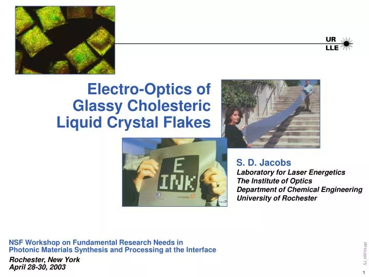
Electro-Optics of Glassy Cholesteric Liquid Crystal Flakes. S. D. Jacobs Laboratory for Laser Energetics The Institute of Optics Department of Chemical Engineering University of Rochester. NSF Workshop on Fundamental Research Needs in Photonic Materials Synthesis and Processing at the Interface

E N D
Electro-Optics ofGlassy CholestericLiquid Crystal Flakes S. D. JacobsLaboratory for Laser EnergeticsThe Institute of OpticsDepartment of Chemical EngineeringUniversity of Rochester NSF Workshop on Fundamental Research Needs inPhotonic Materials Synthesis and Processing at the Interface Rochester, New YorkApril 28-30, 2003
Summary and Outline GOAL: To control motion and optical properties of GCLC flakes using an electric field • GCLC flakes exhibit selective reflection that can be modulatedby controlling flake orientation • Theory of particle electromechanics is extended to GCLCflake motion • Experiments confirm theoretical predictions based on 2D and3D models • Flake motion depends upon electric field frequency and magnitude • Host fluid properties influence reorientation time and determine electric field regime required for flake motion • Flake shape and size affect reorientation time • GCLC flakes have many applications, most prominently forelectronic ink
1 cm 2.5 cm 70 mm Flakes are Produced by Fracturing a GCLC FilmDeveloped In Early 1990’s • The initial form is a polycrystalline solid* • CLC characteristics • A Solvent-free film cast on a silicon substrate at an elevated temperature • Liquid nitrogen is poured over the substrate, and the film fractures, forming flakes Photo of flakes by E. Korenic *Polysiloxane materials provided by Dr. F. Kruezer, Wacker-Chemie, Consortium für Electrochemische Industrie GmbH.
Knife Coated / Freeze Fractured FlakesRandom Shapes, Different Sizes and Thicknesses Leica 160X and 320X SEM 500X and 2000X Thicknesses: 10.9, 12.6 and 54.5 µm Manufactured by E. Korenic
Commercial FlakesRandom Shapes and Surface Textures 800X 320X From Wacker-Chemie, Munich, Germany Leica, pol. microscope
Thicknesses of Commercial Flakes Vary byMore Than 50% From Wacker-Chemie, Munich, Germany SEM, 500X and 3000X Thicknesses: 5 and 7.9 µm
Current Applications for Flakes AreMainly Decorative • Flakes are suspended in host binders for use as pigments in paints and polishes • Brilliant colors result from the selective reflection effect Photos by E. Korenic, Ph.D. Thesis, University of Rochester, 1997.
Selective Reflection in Cholesteric LC’s is a Bragg-like Effect Fergason’s equation -for wavelength of maximum reflection yellow green blue
FIELDOFF v Glass ITO Host fluid Flake FIELDON + v - Concept for an Electro-Optic GCLC Flake Device Suspension in host fluid allows electric field manipulation of flakes* Bright selective reflection color is shifted and diminished when flakes rotate * T. Kosc, et al., US Patent allowed and to be issued.
+ + - - - - - - - - - - + + + + + + + + + + _ _ t2 > t1 V = Vo t1 > t0 V = Vo t0 = 0 V = 0 Why Would Dielectric Particles in a Host Fluid Move when an Electric Field is Applied? • Maxwell-Wagner polarization explains observations • Electric field inside a dielectric particle varies from the applied electric field • Charge accumulates at the boundary of the particle and host fluid • Interfacial polarization and a dipole moment are induced • Applied electric field acts on particle with induced dipole moment
Modeling Done to Determine Equation of Motion* From Torques Acting on a Flake Electrostatic Torque Hydrodynamic Torque ai Particle axis Ai Elliptical function ho Kinematic viscosity of host fluid wi Angular velocity relative to axis, xi e* Dielectric constant Ki* Clausius-Mosotti function Assume particle has no permanent dipole moment. The moment of inertia is negligible in this heavily damped system, giving *based on: Okagawa, et al., J. of Colloid and Interface Sci. 47 (2), 536-567 (1974). Jones, Electromechanics of Particles (New York: Cambridge Univ. Press, 1995).
z E z ´ j y ´ j y x, x ´ Consider Rotation About Longest Axis (1) toFind Time for 90° Reorientation Write equation for angular velocity (for q = 0) Integrate to solve for time, t Axis definitions: 1 -> x’ 2 -> y’ 3 -> z’ Initial angle = o
Key Parameters are revealed in Equation for Reorientation Time • Initial Flake Orientation () • Host Fluid Viscosity ( - linear) • Conductivities (K2*, K3*) • Electric Field Frequency (K2*, K3*) • The Clausius-Mossotti function measures the strength of the polarization and becomes complex when non-ideal dielectrics with loss are considered • Electric Field Magnitude (Eo - inverse quadratic) • Dielectric Permittivities (h, K2*, K3*) • Three Flake Dimensions (a2, a3, A2, A3)
What Is a Reasonable Reorientation Time? • Fluid Properties • sh = 5x10⁻⁴ S/m eh = 69eo C2/Nm2 • ho = 2.9 cSt • Flake Properties • sp = 0 • ep = 3 eo C2/Nm2 • a1 = 60 µm • a2 = 20 µm • a3 = 6 µm Electric Field V = 2.3 Vrms d = 43 µm Reorientation timet ~ 450 ms Now, Can We See Flake Motion?
Using a Moderately Conductive Host Fluid, Flakes Complete 90° Reorientation in the AC Field Regime Using propylene carbonate as a host (s~ 10-4 S/m), driving fields are on the order of tens to hundreds of mVrms/µm • Many flakes “flicker”: a second flash of color is seen as they reorient • Flakes relax to their original orientation within minutes after the applied field is turned off • Though flake motion is not well controlled in DC fields, the regime is worth pursuing because it may hold promise for bistability Before ~ 35 mVrms/µm at 70 Hz ~ 170 mVrms/µm at 70 Hz 150 µm
Using a Moderately Conductive Host Fluid, Flakes Complete 90° Reorientation in the AC Field Regime Using propylene carbonate as a host (s~ 10-4 S/m), driving fields are on the order of tens to hundreds of mVrms/µm • Many flakes “flicker”: a second flash of color is seen as they reorient • Flakes relax to their original orientation within minutes after the applied field is turned off • Though flake motion is not well controlled in DC fields, the regime is worth pursuing because it may hold promise for bistability After ~ 35 mVrms/µm at 70 Hz ~ 170 mVrms/µm at 70 Hz 150 µm
Optical System for Quantifying Motion of a Single Flake by Reflected Signal Amplitude and Frequency Viewing: normal to cell plane Fiber Optic (Not drawn to scale) Power Supply Precision fiber coupler PMT Oscilloscope Iris Microscope * Cell Function Generator Amplifier * Polarizing white light microscope in reflection, typically at 100x
A Flake with a 60 µm Long Dimension Reorients within ~ 500 ms in a 170 mvrms/ µm Field • Flakes are rotating 90° instead of just tipping • A second intensity spike is due to higher order selective reflection effects • Contrast ratios as large as 15:1 have been measured for a single flake, with no attempt to eliminate light from other flakes and sources of scatter Dt • Dt - time delay for flake motion to start • Rt - time for flake to rotate between maximum and minimum reflectivity Rt
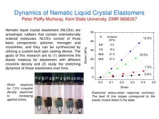
Experimental Data Show an Inverse Quadratic Dependence on the Applied Field • Log-log scale (insert) shows theoretical fit to data obtained by entering actual particle and host fluid material and dielectric property values Line of slope = -2 R2 = 0.78
The Imaginary Component of the Clausius-Mossotti Function Helps Explain Frequency Dependence • The imaginary component contains phase information resulting from the cross product of the applied electric field and the induced dipole moment
Flake Shape andSize Affect Reorientation Time • Flakes with the largest aspect (length to width) ratio reorient the fastest • The curve is based on our model, holding the flake length constant while the width is varied Flake Surface Shapes Are Drawn Advantages to Controlling Flake Size and Shape
Square Patterned Flakes Show Fast, Uniform Reorientation with Little Edge Light Scattering • 80 µm flakes reorient in 300-500 ms • Propylene carbonate host, 140 µm cell • Electric field ~ 40 mVrms/ µm at 70 Hz 100 µm Before • Flakes do not translate once reorientation is complete • Flakes edges are tapered so little edge scatter is seen • Flakes relax in approximately 30 seconds
Square Patterned Flakes Show Fast, Uniform Reorientation with Little Edge Light Scattering • 80 µm flakes reorient in 300-500 ms • Propylene carbonate host, 140 µm cell • Electric field ~ 40 mVrms/ µm at 70 Hz 100 µm After • Flakes do not translate once reorientation is complete • Flakes edges are tapered so little edge scatter is seen • Flakes relax in approximately 30 seconds
12 µm Shaped Flakes Show Good Reproducibility in Shape Uniformity Square (160X,800X) Rectangular (320X,800X) Diamond (160X,800X) Leica, polarizing microscope
Commercial:Shaped: P-V [nm] 1300 1200 430 400 RMS [nm] 260 230 110 100 12 µm Surface Roughness (P-V and RMS) for Commercial Flakes orKnife-Coated Flakes are Much Larger Than That for Shaped Flakes Average of 10 measurements on 5 flakes of each type, line scan=12µm, unfiltered Zygo, NewView 5000, 40X Mirau
Shaped FlakesCharacterized by SEM Squares Dimensions = 14.8 µm / 10.7 µm Thickness = 3.73 µm Layered structure SEM, 5000X
The Unique Properties of Switchable GCLC Flakes Provide a Host of Possible Applications • Electro-Optics and Photonics • Switchable and tunable color filters, optical retarders, micropolarizers and modulators with unique polarizing, reflection and transmission properties • Military/Security • Vehicle camouflage, patterned particles for storage of encoded and encrypted information • Coatings Technology • Environmentally robust switchable “paints” or conformal coatings, switchable “smart windows” for energy or privacy control • Information Display • Reflective multi-color information displays, flexible media for information display on either flat or curved surfaces,“electronic paper”
1973: N. Sheridon created the first “electronic letter” in history at Xerox PARC (“Gyricon”) 1995-1997: J. Jacobson begins work on creating an “electronic book” at MIT Media Lab, founds E-Ink Brief Evolution of “Electronic Paper”Display Technology 2000: Xerox spins off “Gyricon Media”, licenses technology to 3M for manufacturing
How Does GCLC Flake Technology Compare with Other Particle Display Technologies? • Functions due to a physical mechanism based on an induced dipole moment, not electrophoresis and/or a permanent dipole moment • Requires drive voltages at least an order of magnitude lower • Offers color and polarization effects without additional filters or polarizers • Approaches the switching times for the current leading particle displays, which are on the order of 30 - 300ms Key Attributes to Be Demonstrated Using New GCLC Materials:Motion Reversal, Bistability, and Micro-Encapsulation
Direction for Future Research • A method or mechanism to drive GCLC flakes back to their original position • A method or mechanism for bistability • New materials for use as host fluids or for altering dielectric properties of GCLC flakes • New driving schemes for GCLC flake cells (devices) • Micro-encapsulation and other methods forisolating flakes • Theoretical work
Acknowledgements • Dr. Tanya Kosc, Laboratory for Laser Energetics • Mr. Ken Marshall, Laboratory for Laser Energetics • Prof. John Lambropoulos, Dept. Mechanical Engineering,University of Rochester • Mr. Bob Boni, Laboratory for Laser Energetics • Mr. Brett Klehn, Rochester Institute of Technology • Prof. Tom Jones, Dept. Electrical and Computer Engineering, University of Rochester Financial support form: • Laboratory for Laser Energetics, University of Rochester • Reveo Inc., Hawthorne, NY • The Center for Electronic Imaging Systems,University of Rochester