Download
1 / 73
1.08k likes | 2.2k Views
The Physics of Diagnostic Ultrasound FRCR Physics Lectures. Session 3 & 4. Mark Wilson Clinical Scientist (Radiotherapy). mark.wilson@hey.nhs.uk. Hull and East Yorkshire Hospitals. NHS Trust. Session 3 Overview. Session Aims: Recap Image Artefacts Contrast Agents

E N D
The Physics of Diagnostic UltrasoundFRCR Physics Lectures Session 3 & 4 Mark Wilson Clinical Scientist (Radiotherapy) mark.wilson@hey.nhs.uk Hull and East Yorkshire Hospitals NHS Trust
Session 3 Overview Session Aims: Recap Image Artefacts Contrast Agents Introduction to Doppler US Hull and East Yorkshire Hospitals NHS Trust
Recap Hull and East Yorkshire Hospitals NHS Trust
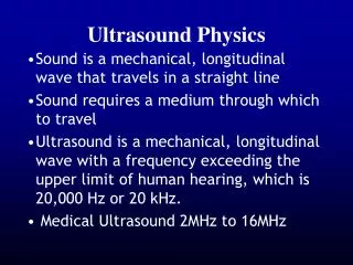
Recap The term Ultrasound refers to high frequency sound waves. Sounds waves are mechanical pressure waves which propagate through a medium causing the particles of the medium to oscillate backward and forward The velocity and attenuation of the ultrasound wave is strongly dependent on the properties of the medium through which it is travelling = c / f c = k / Hull and East Yorkshire Hospitals NHS Trust
Recap D Source of sound ) Sound reflected at boundary ) ) ) Pulse ) Distance = Speed x Time 2D = c x t Echo Diagnostic ultrasound utilises the pulse-echo principle Each pulse-echo sequence produces one line of the image Several pulse-echo sequences are needed to compose a full image frame. Hull and East Yorkshire Hospitals NHS Trust
Recap Ultrasound waves undergo the following interactions: Reflection Scatter Refraction Attenuation and Absorption Diffraction Hull and East Yorkshire Hospitals NHS Trust
( ) 2 Z2 – Z1 Ir R = = Ii Z1 + Z2 Reflection Recap z1 z2 pi , Ii pt , It pr , Ir Intensity Reflection Coefficient (R) Acoustic Impedance z = k Acoustic Impedance z = c Hull and East Yorkshire Hospitals NHS Trust
Recap • Strength of reflection depends on the difference between the Z values of the two materials • Ultrasound only possible when wave propagates through materials with similar acoustic impedances – only a small amount reflected and the rest transmitted • Therefore, ultrasound not possible where air or bone interfaces are present Reflection Hull and East Yorkshire Hospitals NHS Trust
Recap Scatter Reflection occurs at large interfaces such as those between organs where there is a change in acoustic impedance Within most organs there are many small scale variations in acoustic properties which constitute small scale reflecting targets Reflection from such small targets does not follow the laws of reflection for large interfaces and is termed scattering Scattering redirects energy in all directions, but is a weak interaction compared to reflection at large interfaces Hull and East Yorkshire Hospitals NHS Trust
Recap c2 (>c1) c1 Snell’s Law Refraction When an ultrasound wave crosses a tissue boundary at an angle (non-normal incidence), where there is a change in the speed of sound c, the path of the wave is deflected as it crosses the boundary sin (i) c1 i = c2 sin (t) t Hull and East Yorkshire Hospitals NHS Trust
Recap Intensity, I Low freq. Attenuation As an ultrasound wave propagates through a medium, the intensity reduces with distance travelled Attenuation describes the reduction in intensity with distance and includes scattering, diffraction, and absorption Attenuation increases linearly with frequency Limits frequency used – trade off between penetration depth and resolution High freq. Distance, d I = Ioe- d Where is the attenuation coefficient Hull and East Yorkshire Hospitals NHS Trust
Recap Absorption In soft tissue most energy loss (attenuation) is due to absorption Absorption is the process by which ultrasound energy is converted to heat in the medium Absorption is responsible for tissue heating Decibel Notation Attenuation and absorption is often expressed in terms of decibels Decibel, dB = 10 log10 (I2 / I1) Hull and East Yorkshire Hospitals NHS Trust
Image Artefacts Hull and East Yorkshire Hospitals NHS Trust
Artefacts Image Artefacts When forming a B-mode image, a number of assumptions are made about ultrasound propagation in tissue. These include: Speed of sound is constant Attenuation in tissue is constant Ultrasound pulse travels only to targets that are on the beam axis and back to the transducer Significant variations from these conditions in the target tissues are likely to give rise to visible image artefacts Hull and East Yorkshire Hospitals NHS Trust
Artefacts Range Errors The distance, d, to the target is derived from the time elapsed between transmission of the pulse and receipt of the echo from the target, t In making this calculation the system assumes that t = 2d / c, where the speed of sound is constant at 1540 m/s If the speed of sound in the medium between the transducer and target is greater (or less) than 1540 m/s, the echo will arrive back at the transducer earlier (or later) than expected for a target of that range Tissue c = 1540 m/s Fat c = 1420 m/s Target Displayed at Hull and East Yorkshire Hospitals NHS Trust
Artefacts Target Displayed at Medium 1 c1 Refraction Refraction of the ultrasound beam as it passes between tissues with a different speed of sound can result in objects appearing at an incorrect position in the image Medium 2 c2 > c1 Hull and East Yorkshire Hospitals NHS Trust
Artefacts Attenuation Artefacts During imaging the outgoing pulse and returning echoes are attenuated as they propagate through tissue, so that echoes from deeper targets are weaker than those from similar superficial targets Time Gain Compensation (TGC) is applied to correct for such changes in echo amplitude with target depth Most systems apply a constant rate of compensation designed to correct for attenuation in typical uniform tissue The operator can also make additional adjustments to compensate via slide controls that adjust the gain applied specific depths in the image TGC artefacts may appear in the image when the applied compensation does not match that actual attenuation rate in the target tissue Hull and East Yorkshire Hospitals NHS Trust
Artefacts Image of renal cyst Acoustic Enhancement Occurs when ultrasound passes through a tissue with low attenuation Echoes from deeper lying tissues are enhanced due to the relatively low attenuation in the overlying tissue This occurs because the TGC is set to compensate for the greater attenuation in the adjacent tissues Low attenuation Hull and East Yorkshire Hospitals NHS Trust
Artefacts Image of Gallstone High attenuation Acoustic Shadowing Occurs when ultrasound wave encounter a very echo dense (highly attenuating) structure Nearly all of the sound is reflected, resulting in an acoustic shadow This occurs because the TGC is set to compensate for the lower attenuation in the adjacent tissues Hull and East Yorkshire Hospitals NHS Trust
Artefacts Transducer Interface Reverberation Artefact Reverberation artefacts arise due to reflections of pulses and echoes by strongly reflecting interfaces Occur most commonly where there is a strongly reflecting interface parallel to the transducer face Involves multiple reflections - Initial echo returns to reflecting interface as if it is a weak transmission pulse and returns a second echo (reverberation) Reverberation Hull and East Yorkshire Hospitals NHS Trust
Artefacts Attenuation Artefacts Hull and East Yorkshire Hospitals NHS Trust
Artefacts Attenuation Artefacts Hull and East Yorkshire Hospitals NHS Trust
Contrast Agents Hull and East Yorkshire Hospitals NHS Trust
Contrast Agents Ultrasound Contrast Agents Ultrasound contrast agents are gas-filled micro-bubbles which are injected into the blood stream Micro-bubbles will give increased backscatter signal due to the large acoustic impedance mismatch between the gas-filled bubble and surrounding tissue Hull and East Yorkshire Hospitals NHS Trust
Contrast Agents Ultrasound Contrast Agents Micro-bubble suspension is injected intravenously into the systemic circulation in a small bolus The micro-bubbles will remain in the systemic circulation for a certain period of time Ultrasound waves are directed on the area of interest and when the micro-bubbles in the blood flow past the imaging window they give rise to increased signal Allows detection of blood flow where it would otherwise not be seen Hull and East Yorkshire Hospitals NHS Trust
Contrast Agents Ultrasound Contrast Agents Hull and East Yorkshire Hospitals NHS Trust
Contrast Agents Targeted Contrast Agents Targeted contrast agents are under preclinical development They retain the same general features as untargeted micro-bubbles, but they are outfitted with ligands that bind to specific receptors expressed by cell types of interest Micro-bubbles theoretically travel through the circulatory system, eventually finding their respective targets and binding specifically If a sufficient number of micro-bubbles have bound to the target area, an increased signal will be seen Hull and East Yorkshire Hospitals NHS Trust
Doppler Ultrasound Hull and East Yorkshire Hospitals NHS Trust
Doppler Ultrasound The Doppler Effect The Doppler effect is observed regularly in our daily lives, e.g. it can be heard as the changing pitch of an ambulance siren as it passes by The Doppler effect is the change in the observed frequency of the sound wave (fr) compared to the emitted frequency (ft) which occurs due to the relative motion between the observer and the source Consider three situations - Source and observer stationary - Source moving towards observer - Source moving away from observer Hull and East Yorkshire Hospitals NHS Trust
Doppler Ultrasound ) ) Observer ) ) ) fr = ft Source Source and observer stationary The observed sound has the same frequency as the emitted sound (Note: Frequency is the number of cycles per second) Hull and East Yorkshire Hospitals NHS Trust
Doppler Ultrasound ) ) ) ) ) fr > ft Source moving towards observer Causes the wavefronts travelling towards the observer to be more closely packed, so that the observer witnesses a higher frequency wave than emitted Hull and East Yorkshire Hospitals NHS Trust
Doppler Ultrasound ) ) ) ) ) fr < ft Source moving towards observer The wavefronts travelling towards the observer will be more spread out, so that the observer witnesses a lower frequency wave than emitted Hull and East Yorkshire Hospitals NHS Trust
Doppler Ultrasound The Doppler Effect The resulting change in the observed frequency from that transmitted is known as the Doppler shift The magnitude of the Doppler shift frequency is proportional to the relative velocity between the source and the observer It does not matter if it is the source or the observer is moving The Doppler effect enables Ultrasound to be used to assess blood flow by measuring the change in frequency of the ultrasound scattered from moving blood Hull and East Yorkshire Hospitals NHS Trust
Doppler Ultrasound Ultrasound measurement of blood flow Transducer is held stationary and the blood moves with respect to the transducer The ultrasound waves transmitted by the transducer strike the moving blood, so the frequency of the ultrasound experienced by the blood is dependent on whether the blood is stationary, moving towards or away from the transducer The blood then scatters the ultrasound, some of which travels in the direction of the transducer and is detected The scattered ultrasound is Doppler frequency shifted again as a result of the motion of the blood, which now acts as a moving source Therefore, a Doppler shift has occurred twice between the ultrasound being transmitted and received back at the transducer Hull and East Yorkshire Hospitals NHS Trust
Doppler Ultrasound 2 ft v cos Doppler frequency shift, fd = fr – ft = c Target direction fr = received frequency Ultrasound measurement of blood flow ft = transmitted frequency c = speed of sound v = velocity of blood = angle between the path of the ultrasound beam and the direction of the blood flow (angle of insonation) Hull and East Yorkshire Hospitals NHS Trust
Doppler Ultrasound cos 1 Ultrasound measurement of blood flow The detected Doppler shift also depends on the cosine of the angle between the path of the ultrasound beam and the direction of blood flow The operator can alter by adjusting the orientation of the transducer on the skin surface Desirable to adjust to obtain the highest Doppler frequency shift 0 90 Hull and East Yorkshire Hospitals NHS Trust
Doppler Ultrasound c fd v = 2 ft cos Ultrasound measurement of blood flow If the angle of insonation of the ultrasound beam is known it is possible to use the Doppler shift frequency to estimate the velocity of the blood using the Doppler equation In diseased arteries the lumen will narrow and the blood velocity will increase Hull and East Yorkshire Hospitals NHS Trust
Doppler Ultrasound Narrowing in artery V1 V2 A2 A1 Ultrasound measurement of blood flow The flow (Q) remains constant Q =A1 V1 = A2 V2 A = Area V = Velocity Hull and East Yorkshire Hospitals NHS Trust
Break Hull and East Yorkshire Hospitals NHS Trust
Session 4 Overview Session Aims: Continuous Wave Doppler US Pulsed Wave Doppler US Harmonic Imaging Hull and East Yorkshire Hospitals NHS Trust
Doppler Ultrasound Continuous Wave and Pulsed Wave Doppler Doppler systems can be either continuous wave or pulsed wave Continuous wave (CW) systems transmit ultrasound continuously Pulsed wave (PW) systems transmit short pulses of ultrasound The main advantage of PW Doppler is that Doppler signals can be acquired from a known depth The main disadvantage of PW Doppler is that there is an upper limit to the Doppler frequency shift which can be detected Hull and East Yorkshire Hospitals NHS Trust
Doppler Ultrasound Continuous Wave (CW) Doppler In a CW Doppler system there must be separate transmission and reception of ultrasound – transducer with two separate elements The region from which Doppler signals are obtained is determined by the overlap of the transmit and receive ultrasound beams Hull and East Yorkshire Hospitals NHS Trust
Doppler Ultrasound Transducer Gate depth Gate length Pulsed Wave (PW) Doppler In a PW Doppler system it is possible to use the same transducer element for both transmit and receive The region from which Doppler signals are obtained is determined by the depth of the gate and the length of the gate, which can both be controlled by the operator Hull and East Yorkshire Hospitals NHS Trust
Doppler Ultrasound Ultrasound signal received by transducer The received ultrasound signal consists of the following four types of signal: echoes from stationary tissue echoes from moving tissue echoes from stationary blood echoes from moving blood The task for the Doppler system is to isolate and display the Doppler signals from blood, and remove those from stationary and moving tissue Hull and East Yorkshire Hospitals NHS Trust
Doppler Ultrasound Amplitude Tissue Ultrasound signal received by transducer Doppler signals from blood tend to be low amplitude (small reflected echo) and high frequency shift (high velocity) Doppler signals from tissue are high amplitude (large reflected echo) and low frequency shift (low velocity) These differences provide the means by which signals from true blood flow may be separated from those produced by surrounding tissue Blood Frequency Hull and East Yorkshire Hospitals NHS Trust
Doppler Ultrasound Demodulation Separation of the Doppler frequencies from the underlying transmitted signal Transducer Demodulator High-pass filtering Removal of the tissue signal Signal processor Doppler signal processing High-pass filter Frequency estimation Calculation of Doppler frequency and amplitudes Frequency estimator Display Hull and East Yorkshire Hospitals NHS Trust
Doppler Ultrasound Demodulation The Doppler frequencies produced by moving blood are a tiny fraction of the transmitted ultrasound frequency E.g. If transmitted frequency is 4 MHz, a motion of 1 m/s will produce a Doppler shift of 5.2 kHz, which is less the 0.1% of the transmitted frequency The extraction of the Doppler frequency information from the ultrasound signal received from tissue and blood is called demodulation In PW Doppler, need the PRF to be at least twice the maximum Doppler shift frequency in order to avoid ‘aliasing’ (not a problem in CW) Aliasing is an artefact introduced by under-sampling in which high frequency components take the alias of a low frequency component Hull and East Yorkshire Hospitals NHS Trust
Doppler Ultrasound Amplitude Amplitude High-pass Filtering Tissue High-pass Filtering Blood Blood Frequency Frequency Hull and East Yorkshire Hospitals NHS Trust
Doppler Ultrasound Frequency Estimation A spectrum analyser calculates the amplitude of all the frequencies present within the Doppler signal In the spectral display the brightness is related to the amplitude of the Doppler signal component at that particular frequency Frequency shift Time Hull and East Yorkshire Hospitals NHS Trust
Doppler Ultrasound Original signal Aliased signal Aliasing Hull and East Yorkshire Hospitals NHS Trust