Download
1 / 21
210 likes | 367 Views
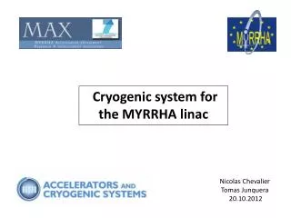
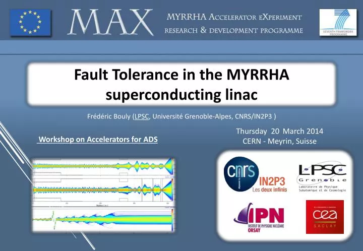
Fault Tolerance in the MYRRHA superconducting linac. Frédéric Bouly ( LPSC , Université Grenoble- Alpes , CNRS/IN2P3 ). Thursday 20 March 2014 CERN - Meyrin , Suisse . Workshop on Accelerators for ADS.

E N D
Fault Tolerance in the MYRRHA superconducting linac Frédéric Bouly (LPSC, Université Grenoble-Alpes, CNRS/IN2P3 ) Thursday 20 March 2014 CERN - Meyrin, Suisse Workshop on Accelerators for ADS
1. Introduction– 2. Linac Design – 3. RF Fault tolerance – 4. Recovery procedures and technological requirements – 5. Conclusions Introduction: A high reliability linac for MYRRHA • Demonstrate the ADS Concept & Transmutation • Coupling : Accelerator + spallation source + subcritical reactor High power proton beam (up to 2.4 MW) Avoid beam trips longer than 3 seconds to minimise thermal stresses and fatigue on target, reactor & fuel assembliesand to ensure 80 % availability. Actual Specification : Less than 10 trips per 3 months operation cycle. Extremereliabilitylevel Reliability guidelines are needed for the ADS accelerator design: Strong design i.e. robust optics, simplicity, low thermal/mechanical stress, operation margins… Redundancy(serial where possible, or parallel) to be able to tolerate failures Repairability(on-line where possible) and efficient maintenance schemes Fault tolerance in the MYRRHA SC linac
1. Introduction– 2. Linac Design – 3. RF Fault tolerance – 4. Recovery procedures and technological requirements – 5. Conclusions Global strategy for faults compensation Strategy for a fault in the injector : Parallel redundancy Operationalinjector 1: RF + PS + beam ON Switchingmagnet Change polarity in ~1s + • R. Salemme : The MYRRHA LEBT test stand • D. Mäder : The MAX injector R&D Warm stand-by injector 2: RF+ PS ON, beam OFF (on FC) Strategy for a fault in the main linac : Serial redundancy & independently powered cavities A failure is detected anywhere Beam is stopped by the MPS in injector at t0 The fault is localized in a SC cavity RF loop Need for an efficient fault diagnostic system New V/φ set-points are updated in cavities adjacent to the failed one Set-points determined via virtual accelerator application and/or at the commissioning phase The failed cavity is detuned (to avoid the beam loading effect) Using the Cold Tuning System Once steady state is reached, beam is resumed at t1 < t0 + 3sec Failed RF cavity system to be repaired on-line if possible Fault tolerance in the MYRRHA SC linac
1. Introduction – 2. Linac Design – 3. RF Fault tolerance – 4. Recovery procedures and technological requirements – 5. Conclusions Consequences on the linac architecture The Local Fault-Recovery scheme A minimal number of cavity settings need to be modified Significant cavity Voltage increase (up to ~30%) needed for compensation Efficient SC cavities initially used at half of their capabilities in nominal conditions – Ability for fast field increase in CW (no multipacting, low field emission…) Fast tuning system for failed cavity detuning & to minimise RF power consumption Large acceptance for phase retuning and margins on the available RF power • Followed rules for the longitudinal beam dynamics design • 1. Keep phase advance at zero-current σL0 < 90° / lattice • → GOAL = avoid SC-driven parametric resonances & instabilities in mismatched conditions • → Implies limitations on Eacc • 2. Provide high longitudinal acceptance • → GOAL = avoid longitudinal beam losses & easily accept fault conditions • → Implies low enough synchronous phases (φs= -40° at input, keep φs< -15°) & to keep constant phase acceptance through linac, especially at the frequency jump • 3. Continuity of the phase advance per meter (< 2°/m) • → GOAL = minimize the potential for mismatch and assure a current independent lattice • → Implies especially limitations on Eaccat the frequency jump J-L. Biarrotte: Talk at SLHiPP2, Catana Fault tolerance in the MYRRHA SC linac
1. Introduction – 2. Linac Design – 3. RF Fault tolerance – 4. Recovery procedures and technological requirements – 5. Conclusions Linac architecture • 5-ELLIPT47 2 cav/module2-SPOKE50 (ESS) is also a viable back-up candidate • 5-ELLIPT654 cav/module • 1-SPOKE352 cav/module *Eacc is given at βoptnormalisedto Lacc = Ngap.β.λ/2 • Overall linac: 233 metres & 142 cavities J-L. Biarrotte et al., Proc. SRF 2013 Fault tolerance in the MYRRHA SC linac
1. Introduction – 2. Linac Design – 3. RF Fault tolerance – 4. Recovery procedures and technological requirements – 5. Conclusions Beam dynamics simulations • Rules for transverse beam dynamics • Keep phase advance at zero-current σT0 < 90° / lattice to avoid structure and Space charge driven resonances • Keep σT > 70% σLto stay away from the dangerous parametric resonance σT = σL/2 • Avoid emittance exchange between T & L planes via SC-driven resonances • Keep smooth transverse phase advance & provide clean matching between sections in all planes to minimise emittance growth J-L. Biarrotte: Talk at SLHiPP2, Catana J-L. Biarrotte et al., Proc. SRF 2013 Fault tolerance in the MYRRHA SC linac
1. Introduction – 2. Linac Design – 3. RF Fault tolerance – 4. Recovery procedures and technological requirements – 5. Conclusions Beam dynamics and acceptance Transverse and longitudinal lattice phase advance & cavities set points in the Hofmann diagram J-L. Biarrotte et al., Proc. SRF 2013 Transverse acceptance: Ø tube / RMS envelope > 15 • Longitudinal acceptance: • Up to 50 times nominal RMS emittance Fault tolerance in the MYRRHA SC linac
1. Introduction – 2. Linac Design– 3. RF Fault tolerance – 4. Recovery procedures and technological requirements – 5. Conclusions Retuning feasibility and beam dynamics aspects • Preliminary studies on the Retuning procedures with the “perfect” linac design : • Evaluate the retuning feasibility and critical scenario (transitions between two cavity sections, full cryomodule loss…) • Quantify requirement for the RF technologies • keep the acceptance (smooth phase advance, low synchronous phase…) • One example : A complete spoke cryomodule is lost (2 cavities) • Retuning strategy used in the TraceWin code for compensation optimisation Fault tolerance in the MYRRHA SC linac
1. Introduction – 2. Linac Design– 3. RF Fault tolerance – 4. Recovery procedures and technological requirements – 5. Conclusions Retuning example: 1 spoke module lost Max. voltage increase : 27 % Max. synchronous phase : 16° Fault tolerance in the MYRRHA SC linac
1. Introduction – 2. Linac Design– 3. RF Fault tolerance – 4. Recovery procedures and technological requirements – 5. Conclusions Retuning example : 1 spoke module lost Fault-recovery Nominal Tuning Emittances growthalong the linac(RMS) ~+1% Longitudinal acceptance (SC linac + MEBT + HEBT) Fault tolerance in the MYRRHA SC linac
1. Introduction – 2. Linac Design– 3. RF Fault tolerance – 4. Recovery procedures and technological requirements – 5. Conclusions Conclusions on these fault-recovery scenario analyses • Several scenarios studied even with multiple cryomodules failures in different section • The main conclusion is : the fault recovery scheme is a priori feasible everywhere in the MYRRHA main linac to compensate for the loss of a single cavity or even of a full cryomodule. Scenarios with several failed modules already tested. Further studies are required to evaluate the limits of multiple failed cavities/cryomodules. Impact on the R&Dof superconducting cavities and associated systems 1. RF power amplifiers and margins : To take into account errors of control systems & fault recovery 2. PerformantSuperconducting cavities must accept fast gradient changes in CW operation 3. Control systems must enable to : _ Retune the compensation cavities in less than 3 seconds _ frequency detune the failed cavities which could perturb the beam Fault tolerance in the MYRRHA SC linac
1. Introduction – 2. Linac Design – 3. RF Fault tolerance – 4. Recovery procedures and technological requirements – 5. Conclusions RF Power Needs • Power delivered to the beam : • RF power required for a cavity which has an optimum frequency tuning : • Optimal incident coupling : Ideally, each cavity has an optimal Qi (function of (r/Q), ϕs, Vcav & Ib0) 5-cell (βg = 0.47) • Coupling for the 3 cavity families of the MYRRHA accelerator: • Spoke (βg 0.35) : Qi = 2.2 106 BandWidth = 160.2 Hz • 5-cell (βg 0.47) : Qi = 8.2 106 BandWidth= 86.05 Hz • 5-cell (βg 0.65) : Qi = 6.9 106 BandWidth= 102.2 Hz Qi = 8.2 106 Fault tolerance in the MYRRHA SC linac
1. Introduction – 2. Linac Design – 3. RF Fault tolerance – 4. Recovery procedures and technological requirements – 5. Conclusions Estimation of needs due to errors • RF generator power - general formula : Ex : Cavity n° 76 (βg0.47) which is compensating a failure • Errors taken into account for statistical errors study : Uniform Distribution 22.35 kW • 2.106 draws • Vcav : ± 2% • ϕs : ± 2° • Ib0 : ± 2% • Δf : ± 20 Hz • Qi : ± 2 mm (± 20%) • (r/Q) : ± 10 % ~ 7% • + 10 % marginsaddedto errors study to take into account attenuation and calibration errors. Maxi. 24.9 kW ~ 18.5% Fault tolerance in the MYRRHA SC linac
1. Introduction – 2. Linac Design – 3. RF Fault tolerance – 4. Recovery procedures and technological requirements – 5. Conclusions • See presentation RF Power Requirements Minimum RF spare +70% • 75 % Margin forseen • Needs for reliable and flexible power supplies : with possibility for online reparability In MAX R&D on 700 MHz solid-state amplifiers 5-cell β 0.65 Spoke β 0.35 • S. Sierra : Development of 700MHz SS amplifiers 5-cell β 0.47 Fault tolerance in the MYRRHA SC linac
1. Introduction – 2. Linac Design – 3. RF Fault tolerance – 4. Recovery procedures and technological requirements – 5. Conclusions Control Systems requirements • Requirement on Energy accuracy : 600 MeV ± 1 MeV at the linacouput . • Control systems must ensure the stability of the accelerating field and the synchronous phase • With a limited amount of CW power the mechanical frequency tuning systems must enable to retune the compensation cavities and quickly detune the failed ones. • Study the feasibility of retuning procedures (< 3 sec.) for the individually controlled cavities with a limited margin of CW RF power. • Worked based on the β 0.47 linac section • Model : cavity + tuning system + feedback/control loops • Use of MatlabSimulinkTM for time simulation • Define the best control strategy for the tuning system - R&D on an adaptive & predictive controller (ADEX). Fault tolerance in the MYRRHA SC linac
1. Introduction – 2. Linac Design – 3. RF Fault tolerance – 4. Recovery procedures and technological requirements – 5. Conclusions Complete board with analogue mezzanine Control scheme for a superconducting cavity • Model of digital system in I/Q formalism - Transfer function in Laplace domain: • Numerical system effects : Delay + ZOH + modulator. • PI correctors adjusted to minimise beam loading effect. • C. Joly : DLLRF for reliability-oriented linacs • Transfer function of the cold tuning system modelled from measurements • Simualtions for feasibility studies achieved with a PI controller Fault tolerance in the MYRRHA SC linac
1. Introduction – 2. Linac Design – 3. RF Fault tolerance – 4. Recovery procedures and technological requirements – 5. Conclusions A fault recovery scenario • Compensation cavity can be easily retuned in less than100 ms -45 Fault tolerance in the MYRRHA SC linac
1. Introduction – 2. Linac Design – 3. RF Fault tolerance – 4. Recovery procedures and technological requirements – 5. Conclusions Failed cavity and requirement on the cold tuning system • If the cavity is still superconducting, the important criterion is the induced decelerating voltage (to be lowered below 0.5% of nominal voltage); otherwise, it is the dissipated power, especially for a quenched but still cold cavity. • Requirement : • Cavity frequency must be detune by more than 100*BandWidth in less than 3 seconds • Minimum detuning speed capabilities for the CTS: 5 kHz/sec Fault tolerance in the MYRRHA SC linac
1. Introduction – 2. Linac Design – 3. RF Fault tolerance – 4. Recovery procedures and technological requirements – 5. Conclusions Controller of the tuning system • An adaptive and predictive system (from ADEX) was chosen to improve the cavity frequency control (michrophonics damping – fast detuning) • I. Martin Hoyo: C&C activities for cold tuning systems Example: Simple frequency control Example: strong microphonics perturbations Fault tolerance in the MYRRHA SC linac
1. Introduction – 2. Linac Design – 3. RF Fault tolerance – 4. Recovery procedures and technological requirements – 5. Conclusions A real scale experiment Dispose of a “real scale” experimental facility to Carry out Reliability-oriented experiments with a fully-equipped 700 MHz prototypical cryomodule controlled by feedback systems (RF and Fast Cold Tuning System). Component robustness retuning procedures • M. El Yakoubi: the MAX 700MHz test stand Fault tolerance in the MYRRHA SC linac
1. Introduction – 2. Linac Design – 3. RF Fault tolerance – 4. Recovery procedures and technological requirements – 5. Conclusions Conclusions • Fault tolerance studies involved many instrumentation developments for experimental demonstration (real-scale cryomodule, Digital LLRF, Control systems for cavity frequency tuning, solid state amplifier) • Based on existing systems a model of the cavity and its feedback loops have been developed • Results from simulations showed that it is feasible to retune the cavities in less than 3 seconds. • Need fast tuning system to unable the fault recovery procedure to minimise beam loading in the failed cavity. In worst case, the minimum required detuning (>100*Bandwidth)has to be achieved in less than 3 seconds. • These Procedures were defined with beam dynamics simulations. The retuning strategy has been successfully assessed in several test scenarios: RF cavities but also for quads failure. • It rests upon a consolidated superconducting linear accelerator design with large transverse and longitudinal beam acceptances. • Several steps of this procedure appear to be non straightforward and will require further studies (consolidate errors studies, retuning with non-homogenous cavity gradients distrib.,….) • FUTUR WORK : Development of a dedicated retuning tool. Fast calculation of retuning setpoints from actual cavity working points. • Idea : Adjust the voltage, the phase and smooth the phase advance cavity /cavity THANK YOU ! Fault tolerance in the MYRRHA SC linac