Download
1 / 84
930 likes | 1.35k Views
TRANSDUCERS. Device that converts one form of energy to another form for various purposes including measurement or information transfer. Energy may be of any kind electrical, mechanical, chemical, optical. Basic Requirements of transducers. Linearity : i/p – o/p characteristics should

E N D
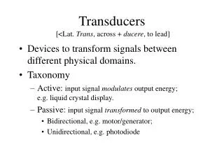
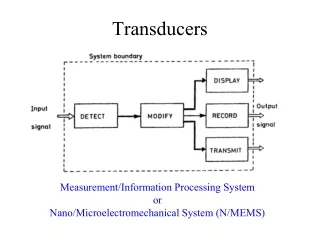
TRANSDUCERS • Device that converts one form of energy to another form for various purposes including measurement or information transfer. • Energy may be of any kind electrical, mechanical, chemical, optical.
Basic Requirements of transducers • Linearity : i/p – o/p characteristics should be linear. • Stability : o/p should be stable to change in temp & other environmental factors. • Ruggedness : capable of withstanding overloads, with measures of overload protection. • Repeatability : should produce identical output signals. • Dynamic Response: should respond to changes in i/p as quickly as possible. • Reliability: should withstand mechanical strains without affecting the performance of the transducer.
Active Transducers self generating, does not require external source. Thermocouple Photovoltaic Cell Piezoelectric Transducer Passive Transducer Requires an external power source. Resistive Transducer Strain Gauge, Thermister, Thermometer. Inductive Transducer Linear Variable Differential Transducer Capacitive Transducer Photoemissive Cell Photomultiplier Tube Classificationof Transducers
Strain Gauge • A device whose electrical resistance varies in proportion to the amount of strain in the device. • The sensitivity of stain gauge is described in terms of Gauge factor. • Gauge factor-Change in resistance per unit change in length. G = ΔR/R = ΔR/R Δl/lS
Bonded strain gauge • Consist of a grid of fine resistance wire cemented to the base. • Base may be thin sheet of paper or bakelite. • Covered with thin sheet of paper or thin bakelite sheet to avoid mechanical damage. • Bonded to the structure under study with an adhesive.
Unbonded strain gauge • Unbonded strain gages consist of a wire stretched between two points • Force acting on the wire (area = A, length = L, resistivity = r) will cause the wire to elongate or shorten. • This will cause the resistance to increase or • decrease proportionally according to: R = ρL/A and ΔR/R = GF· ΔL/L, where GF = Gauge factor (2.0 to 4.5 for metals, and more than 150 for semiconductors).
Thermistor • Two terminal resistor whose resistance changes significantly when its temperature changes. • The resistance of a thermistor decreases with increase of temperature. • Resistance at any temp is given by RT=R0 exp β(1/T-1/T0) Where RT = thermister resistance at temp T(K) R0 = thermister resistance at temp T0(K) β = A constant determined by calibration.
Three parameters characterizing the thermistor are • Time Constant - time for thermistor to change its resistance by 63%.(1 to 50ms) • Dissipation Constant - power necessary to increase the temp of thermistor by 1ºC.(1 to 10 mW/ºC) • Resistance Ratio - ratio of resistance at 25ºC to that at 125ºC.(3 TO 60). • Uses: To measure temp, flow, pressure, composition of gases, liquid level etc.
Thermocouple • Junction between to dissimilar metals or semiconductors that generates a small voltage. • The two junctions reference and sensing are maintained at different temp. • Each junction is made by welding the two dissimilar metals together. • Reference junction has a fixed temp usually 0ºC. • And the output voltage depends on the temp of sensing junction.
Thermocouple circuit iron Reference junction constantan iron Milli voltmeter Sensing junction constantan
Inductive Transducers • In the first diagram the variable inductor is part of an oscillator circuit. • If the position of the core is moved then the oscillator frequency changes. • The change in frequency can be displayed as a change in millimetres.
Variable reluctance type • As the air gap changes the reluctance of the circuit changes. • This causes a change of inductance.
This can be used as shown by the next illustration. • As the inductance changes so the frequency of the oscillator changes. • The output of the oscillator can be converted to DC for display on a digital meter calibrated in inches etc.
Linear Variable Differential Transformer • There is one primary and two secondary windings. • If AC is applied to the primary then voltages are induced in the secondaries. • The secondaries are connected so their outputs are opposite. • When the core is central the two voltages are equal in amplitude and cancel out.
LVDT • If the core is moved then there will be more voltage in one secondary than the other. • The voltages will not cancel out and there will be an AC signal at the output proportional to the distance the core has moved. • Using a phase detector circuit it is also possible to indicate the direction the core has moved. • The graph representation shows the output voltage/position characteristics.
LVDT Model Graph
LoadCell • A loadcell is typically an electronic device that is used to convert a force into an electrical signal. • This conversion is indirect and happens in two stages. • Through a mechanical arrangement, the force being sensed deforms a strain gauge. • The strain gauge converts the deformation (strain) to electrical signals.
Normally, a load cell consists of four strain gauges in a Wheatstone bridge configuration, but is also available with one or two strain gauges. • The electrical signal output is normally in the order of a few millivolts and requires amplification by an instrumentation amplifier before it can be used. • The output of the transducer is plugged into an algorithm to calculate the force applied to the transducer.
Pyrometer • It’s a non-contact instrument that detects an object's surface temperature by measuring the temperature of the electromagnetic radiation (infrared or visible) emitted from the object. • The wavelength of thermal radiation ranges from 0.1 to 100 µm i.e., from the deep ultraviolet (UV) across the visible spectrum to the middle of the infrared region (IR).
Pyrometers are essentially photo detectors which are capable of absorbing energy, or measuring the EM wave intensity, at a particular wavelength or within a certain range of wavelengths.
Common pyrometers include: • Optical Pyrometer : - Designed for thermal radiation in the visible spectrum. - Utilizes a visual comparison between a calibrated light source and the targeted surface. - When the filament and the target have the same temperature, their thermal radiation intensity will match causing the filament to disappear as it blends into the targeted surface in the background. - When the filament disappears, the current passing through the filament can be converted into a temperature reading.
Infrared Pyrometer: - Designed for thermal radiation in the infrared region usually 2 ~ 14 µm - Constructed from pyroelectric materials, e.g., triglisine sulfate (TGS), lithium tantalate (LiTaO3), or polyvinylidene fluoride (PVDF). - Similar to the charge generated by stressed piezoelectric materials, a pyroelectric charge dissipates in time. - Hence, a rotating shutter is required to interrupt the incoming radiation to obtain a stable output.
Advantages: • Fast response time • Good stability • Non-contact measurement • Disadvantages: • Expensive • Accuracy maybe affected by suspended dust, smoke, and thermal background radiation
The Variable Area flowmeter • Also known as Rotameter, is one of the most economical and reliable of flow measurement instruments. • In various configurations it can be designed to withstand high pressures, corrosive fluids, high temperatures, and is completely independent of factors influencing electronic meters. • This is done using a uniformly tapered tube, a float whose diameter is nearly identical to the tube ID at the inlet, and a scale to correlate float height.
The flow tube is traditionally placed in a vertical position and fluid enters from the bottom, forcing the float up in the tube until a sufficient annular opening exists between the float and tube to allow the total volume of fluid to flow past the float. • At this point the float is in an equilibrium position and its height is proportional to the flow rate.
Depending on working principle Moving iron type instruments a). Attraction type b). Repulsion type Moving coil type instruments a). Permanent magnet type b). Dynamometer type
MOVING IRON INSTRUMENTS – ATTRACTION TYPE Principle A soft iron piece gets magnetized when it is brought into a magnetic field produced by a permanent magnet. The same phenomenon happens when the soft iron piece is brought near either of the ends of a coil carrying current. The iron piece is attracted towards that portion where the magnetic flux density is more. This movement of soft iron piece is used to measure the current or voltage which produces the magnetic field.
A soft iron disc is attached to the spindle To the spindle, a pointer is also attached, which is made to move over calibrated scale The moving iron is pivoted such that it is attracted towards the center of the coil where the magnetic field is maximum Construction
Principle • When the current to be measured is passed through the coil or solenoid, field is produced which attracts the eccentrically mounted disc inwards, thereby deflection the pointer which moves over a calibrated scale
Deflecting Torque Produced by the current or the voltage to be measured. It is proportional to the square of the voltage or current. Hence, the instrument can be used to measure d.c. or a.c. Scale is non- uniform Control torque : Spring or gravity Damping : Air friction damping
MOVING IRON INSTRUMENT - REPULSION TYPE Principle • Two iron piece kept with close proximity in a magnetic field get magnetized to the same polarity. Hence, a repulsive force is produced. • If one of the two piece is made movable, the repulsive force will act on it and move it on to one side. • This movement is used to measure the current or voltage which produces the magnetic field.
Construction • There are two iron pieces-fixed and moving. • The moving iron is connected to the spindle to which is attached a pointer. It is made to move over a calibrated scale.
Working • When the current to be measured is passed through the fixed coil it sets up its own magnetic field which magnetizes the two rods similarly the adjacent points on the lengths of the rods will have the same magnetic polarity. • Hence, they repel each other with the result that the pointer is deflected against the controlling torque of a spring or gravity. • The force of repulsion is approximately proportional to the square of the current passing through the coil • Whatever be the direction of current in the coil, the two irons are always similarly magnetised.
Deflecting torque • Produced by the current or the voltage to be measured. • It is proportional to the square of the voltage or current. • Hence, the instrument can be used to measure d.c. or a.c. Control torque : Spring or gravity Damping : Air friction damping
Advantages and disadvantages: • The instruments are cheap ,reliable and robust • The instruments can be used on both A.C and D.C • They cannot be calibrated with high degree of precision with D.C on account of the effect of hysteresis in the iron rods or vanes .
MOVING COIL INSTRUMENT – PERMANENT MAGNET TYPE Principle : when a current carrying conductor is placed in magnetic field it is acted upon by a force which tends to move it to one side and out of the field. This movement of coil is used to measure current or voltage.
This instrument consists of a permanent magnet and a rectangular coil of many turns wound on a light aluminium or copper former inside which is an iron core Construction • The sides of the coil are free to move in the two air gaps between the poles and core • To the moving coil spindle is attached, a pointer is attached to the spindle to move over a calibrated scale.
Working • A magnetic field of sufficient density is produced by the permanent magnet. • The moving coil carries the current or a current proportional to the voltage to be measured. • Hence, an electromagnetic force is produced which tends to act on the moving coil and moves it away from the field. • This movement makes the spindle move and so the pointer gives a proportionate deflection
Deflecting torque : It is directly proportional to the current or the voltage to be measured. So, the instrument can be used to measure direct current and dc voltage. • Control torque : Spring control. • Damping torque : Eddy current damping.Damping is electromagnetic by eddy currents induced in the metal frame over which the coil is wound. Since the frame moves in an intense magnetic field, the induced eddy currents are large and damping is very effective.
The permanent-magnet moving coil (PMMC) type instruments have the following advantage and disadvantages: ADVANTAGES 1. They have low power consumption 2. Their scales are uniform and can be designed to extend over and arc of 1700 degree or so 3. They possess high (torque/weight) ratio. 4. They can be modified what the help o f shunts and resistances to cover a wide range of currents and voltages. 5. They have no hysteresis loss. DISADVANTAGES 1. Due to delicate construction and the necessary accurate machining and assembly of various parts, such instruments are somewhat costlier as compared to moving iron instruments. 2. Some errors are set in due to the ageing of control springs and the permanent magnets.
MOVING COIL INSTRUMENTS – DYNAMOMETER TYPE Principle An electrodynamic instrument is a movingcoil instrument in which the operating field is produced, not by a permanent but by another fixed coil. This instrument can be used either as an ammeter or voltmeter but is generally used as a wattmeter.
Fixed coil (F) is made in two sections. In the space between two, Moving coil (M) is placed. Moving coil is attached to the spindle to which pointer is attached. The pointer is allowed to move over a calibrated scale Construction
Working • The fixed coil and the moving coil carry currents. Thus, two magnetic fields are produced. • Hence, an electromagnetic force tends to act on the moving coil and makes it move. • This makes the pointer gives a proportionate deflection.
Deflecting torque As voltmeter: The two coils are electrically in series. Deflecting torque is proportional to square of voltage to be measured. Hence used for measuring ac and dc voltages. As ammeter: The two coils are electrically in series. Deflecting torque is proportional to square of current to be measured. Hence used for measuring ac and dc currents. As wattmeter: Fixed coils carry the system current. Moving coil carries a current proportional to the system voltage. The deflecting torque is proportional to V ICosφ i.e. Power to be measured Control torque : Spring control. Damping torque : Air damping.