Download
1 / 35
400 likes | 630 Views
Reactor Design I. O2 Transfer. Reactor Design Considerations. The reactor: Must provide for O 2 transfer (or exclusion) Must provide for heat transfer Must provide for sterilization of media Must provide for monitoring and control Must provide for containment.

E N D
Reactor Design I O2 Transfer
Reactor Design Considerations • The reactor: • Must provide for O2 transfer (or exclusion) • Must provide for heat transfer • Must provide for sterilization of media • Must provide for monitoring and control • Must provide for containment
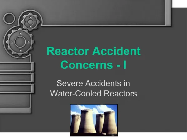
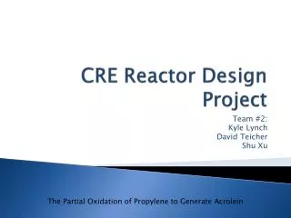
Oxygen-Agitation Recording DO Reading In %
DO reading • The Dissolved Oxygen (DO) reading is a relative measure of the concentration of O2 in the liquid phase of the fermentation media. • When the DO reading is zero – there is no O2 in the liquid (cells must grow anaerobically or die completely) • When the DO reading is 100% the liquid is completely saturated with O2 (no more will dissolve at that condition)
DO Probe Set-up • Before cells are added to the media it is saturated with O2 by bubbling air through the reactor for 10 – 20 minutes. The DO reading is calibrated to read 100%. It is also calibrated so that if there is no O2 the probe will register 0%. • N2 method • Electrical method • The probe calibration should not be changed after this. • The system is set to control the DO level to always be at or above a certain value relative to saturation (e.g. 30%)
DO progression • There are three periods of oxygen progression. • During the first period, the DO will start out at 100% and will drop toward the set point at an accelerating rate – the agitator speed remains at it’s initial value (100 RPM for example) • During the second period the DO is maintained at the set point value (30%). The RPM increases to try to maintain set point. • When the culture stops growing – the oxygen reading returns to 100%.
Oxygen-Agitation Recording DO Reading In %
Analysis • During the initial period (dropping O2) the cells are consuming the O2 from the liquid a little faster than O2 is being transferred from the air bubbles to the liquid. The concentration of O2 in the liquid drops. • During the second period, the cells are consuming O2 at exactly the same rate as the O2 is being transferred from the bubbles to the liquid. Higher agitation rates are needed to keep up with the ever increasing rate of consumption. • During the third period, the cells stop growing and consuming O2. The rate of O2 transfer from the bubbles is faster than the rate of consumption and the concentration in the liquid rises.
The Oxygen Problem • Under normal conditions (1 atm, 37 C), oxygen is only sparingly soluble in water (7 mg/L = 0.21 m-mole/L = 0.21 umole/cm3) • Cells can be using as much as 500 m-mole/L-hr Conclusion: Only a few seconds of O2 can be stored in water. (see how long you can hold your breath!)
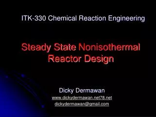
Oxygen Supply • Oxygen is supplied to bioreactors by “sparging” air-oxygen mixtures into the bottom of the reactor to form bubbles. • O2 gas diffuses from the bubble into the fermentation media at a flux given by NO2 = kL(C*-CL) (m-mole-O2/hr/cm2) Where: • C* is the concentration of oxygen in the media (water) in equilibrium with the gas in the bubble (mmole/cm3) • CL is the concentration in the bulk media (what the cells are seeing) (mmole/cm3) • kL is a mass transfer coefficient (cm/hr)
Basic O2 transfer model NO2 = kL(C*-CL) (flux in umole/cm2/hr) kL in cm/hr; C* and CL in umole/cm3 Stagnant film Liquid concentration CL (measured by probe) Air (20% O2 @ 1 atm) Equilibrium Concentration C* = 7 ug/cm3 (saturated vs 1 atm air)
Bubble Area • The total rate at which oxygen can be transferred from the bubbles to the liquid depends on the contact area between the bubbles and the liquid. • The Oxygen Transfer Rate is given by: OTR = kLa(C*-CL) mmoles/L-hr • Where a is the bubble surface area (cm2/cm3 of reactor). The units on a are cm2/cm3 • The units for OTR are m-mole/L-hr
Oxygen Transfer • There are 2 main ways to manipulate the oxygen transfer rate • Change the value of kla by changing the agitation speed (mostly an a effect) • Increase the driving force by: • Letting the concentration of CL in the media drop to a lower level • Increasing the value of the equilibrium C* by: • Increasing the fraction of oxygen in the aeration gas • Increasing the pressure of the aeration gas
kLa • Increasing agitation speed increases both kL and a, but the individual effects are hard to separate. • Correlations are usually for the effects of agitation and gas input rate on the combined term kLa (units hr-1) Thick stagnant film Low RPM Low area Thin stagnant film High RPM High area
kLa vs Agitation • The purpose of agitation is mainly to increase kLa so that faster oxygen transfer can be achieved. kLa ~ KN2.7 Or kLa/(kLa)o ~ (N/No)2.7 Low kLa Low RPM High RPM High kLa
kLa Prediction • To use the previous equation, one must first experimentally measure one kLa at a specified agitation speed for each type and size of reactor. Example: It has been experimentally shown that kLa is 15 hr-1 at 100 RPM in a 5 L reactor, what will the kLa be at 500 RPM? ANS: kLa = 15 hr-1 x (500/100)2.7 = 1156 hr-1
Maximum OTR • The maximum OTR is often used to “rate” a bioreactor. The maximum OTR is the maximum kLa (at a particular agitator speed) times the saturation concentration (0.21 m-moles/L). OTR(max) = kLa*C* For the example with kLa @ 500 RPM = 1156 hr-1: OTR(max) @ 500 RPM = 242 m-moles/L-hr
Gassed Power Input • A better, but more complex way to estimate kLa that does not require any prior experimental data is the gassed power method. • The kla value in mM O2/Liter-hr is linearly correlated to the quantity: (2.0 + 2.8N)(Pg/V)0.77(vs)0.67 Gassed power input in HP/1000L Superficial gas velocity cm/min Number of impeller blades.
kLa Correlation Data WARNING: This is not dimensionless. Exact units used are important!! This is really the OTR max with air as the gas
Gassed Power Input • The gassed power is the power input required to rotate the agitator while gas is flowing • First find the non-gassed power from the reactor Reynolds number (Po) • Next find the gassed power/non-gassed power ratio from the aeration number (Pg/Po) • Compute Pg
Step 1. Determine “Non-gassed” power from power number correlation. Calculate fermentor Reynolds Number Pick off “power number” from Correlation chart Compute Po (non-gassed power) (Units !!!) Step 2. Determine gassed power Calculate aeration number Pick off gassed to non-gassed power ratio from chart Compute Pg (gassed power requirements) (gassed depends on how fast gas is being blown through the reactor) Determination of Power Input
Non-Gassed Power • Power - Re correlation • Dimensionless numbers • Re based on agitation rate • Impeller design
Non-Gassed Power • Tank Reynolds number: NRE = rNDi2/m Rotation speed in rev/time Liquid density Liquid viscosity Impeller diameter
Power Number • Np = Po/rN3Di5 Rotation speed (RPM) Impeller diameter Power required to rotate the shaft Depending on unit system, gc may be needed here
Pg determination • Compute the aeration # and Use chart to find Pg/Po. • Q is the volumetric flow rate of gas through the reactor (m3/s) • NDi3 it the revolution rate in rev/s, times the impeller diameter (in meters) cubed. • From ratio and Po get Pg
Gassed Power • Aeration number: NA = Q/NDi3 Impeller rotation speed Impeller diameter Gas volumetric flow rate
Power input required • Example • Calculate the maximum power required to agitate a 100 L tank with a 20 cm Rushton turbine at 500 RPM • Assume that the tank is supplied with air at “1 vvm” (one volume of air per liter of reactor per minute = 100 LPM) – calculate the necessary gassed power. • Use the gassed power to compute kLa for the reactor. Assume the reactor diameter is 4 x the impeller diameter.
Procedure for kla • Calculate or measure the gassed power input required (Pg) at a given RPM (N)(horsepower) • Divide by the volume of the reactor (V) ( in 1000 ‘s of Liters) • Calculate the superficial gas velocity (vs) (cm/min), volumetric flow rate/reactor cross sectional area.
Scale-up Frequently small scale (5 or 10 L) reactors are used to develop a fermentation process, then a direct scale-up approach is used to design a large scale fermentation. Scale-up dictates that the oxygen demand per unit volume would remain constant. The reactor volume might be scaled up 10 x, the amount of media added 10 x, the input air rate increased 10 x etc. with the expectation that there will be 10 x more cell or cell product produced.
Scale-up problem 10 x Problem areas: Max RPM? Power input? Oxygen transfer rate?
Scale-up • The problems with this approach are: • That the same RPM cannot be achieved in the large reactor (usually large reactors have lower maximum RPM) • That even if the same RPM could be achieved, that the rate of oxygen transfer from the air bubbles to the liquid media may not scale-up • That the scaled large reactor might require an unreasonably large total power input to maintain the oxygen transfer.
Procedure • Use maximum RPM observed in small scale reactor to calculate Po, Pg, and especially kLa. • Use kLa and superficial velocity to calculate needed Pg, Po, and RPM for large reactor. If Pg and RPM are smaller than the maximum values for the reactor the scale-up should work OK. • (Note that there are some more subtle problems with scale-up that have to do with oxygenation zones near the impeller, these may need to be looked into if the calculation is close.)