Download
1 / 14
150 likes | 360 Views
Design of UAV Systems. c 2002 LM Corporation . Aerodynamics . Lesson objective - to review Basic aerodynamics relationships ….the minimum level of fidelity required for pre-concept and conceptual design assessments of subsonic UAVs.

E N D
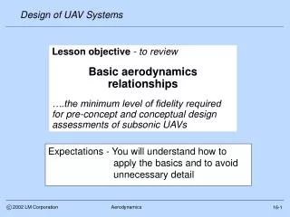
Design of UAV Systems c 2002 LM Corporation Aerodynamics Lesson objective - to review Basic aerodynamics relationships ….the minimum level of fidelity required for pre-concept and conceptual design assessments of subsonic UAVs Expectations - You will understand how to apply the basics and to avoid unnecessary detail 16-1
Design of UAV Systems c 2002 LM Corporation Aerodynamics Importance These are the fundamental aerodynamic relationships needed to define a subsonic air vehicle for a UAV system 16-2
Design of UAV Systems L = lift Swet = Total wetted area excluding inlet and nozzle area Side view Swet-x = Wetted area of x Ai = Inlet area Svt = Exposed VT area V horizon D = Drag = Flight path angle W = weight T = Thrust le = LE sweep Sref = Wing reference area (both sides to CL) cg = center of gravity Anoz = Nozzle area Ct Cr = Root chord Swexp = Exposed wing area (both sides) Cmac = Mean aerodynamic chord Sht = Exposed HT area c 2002 LM Corporation Aerodynamics Cr Cr and geometry Forces Ct 16-3
Design of UAV Systems c 2002 LM Corporation Aerodynamics Aerodynamic lift • Lift (L) = ClqSref = ClqSref (16.1) • Cl = lift curve slope (theoretrical = 2/rad; see • RayAD Eq 12.6 for more exact formulation) • = angle of attack • Sref = aerodynamic reference area • Dynamic pressure (q) = (/2)V^2 (16.2) • = air density (lb-sec^2/ft^4) • V = airspeed (ft/sec) where… and… where… For uncambered airfoils Cl = 0 at = 0 V 16-4
Design of UAV Systems c 2002 LM Corporation Aerodynamics Aerodynamic drag • Drag (D) = CdqSref (16.3) • Cd = drag coefficient • = Cdmin+Cdi = Cdmin+k[Cl-Clmin]^2 (16.4) • k = 1/[Ae] • A = Aspect ratio = b^2/Sref • e = Oswold wing efficiency = f(,A) = sweep • Cdmin = CfKd(Swet/Sref) = Cfe(Swet/Sref) (16.5) • Cf = flat plate skin friction coefficient (See RayAD • Fig 12.21) • Kd 1.2 = Factor to account for non-friction drag • items such as pressure and interference) • Cfe = Equivalent skin friction coefficient (RayAD12.3) where… and … For uncambered airfoil Cdmin = Cd0 where… • These relationships are for “untrimmed” drag polars, good aerodynamic design will minimize trim drag impact (which we will ignore for now) 16-5
Design of UAV Systems c 2002 LM Corporation Aerodynamics Oswold efficiency factor Source - Lee Nicolai, Conceptual Design Process, LM Aero 16-6
Design of UAV Systems Notional Lift Characteristics Nominal Drag Characteristics (uncambered airfoil) 1.4 Clmax 1.2 Max slope = L/Dmax 1.2 slope = Cl 1 1 0.8 0.8 Cdmin CL@ L/Dmax 0.6 0.6 High AR, low sweep 0.4 0.4 Lower AR and/or 0.2 0.2 higher sweep 0 0 0 0.02 0.04 0.06 0 5 10 15 20 CD Alpha (deg) c 2002 LM Corporation Aerodynamics Lift and drag - cont’d • CL and Cdmin are approximately constant for low-to-medium subsonic speed range (below drag rise) • This simplifying assumption makes our aero analysis task really easy (and reasonably correct) 16-7
Design of UAV Systems (L/D)max @ Minimum drag Cdmin = Cdi c 2002 LM Corporation Aerodynamics L/D max - another perspective • Theoretical (L/D)max • If Cd = Cd0 + KCl^2 then D/L = Cd0/Cl + KCl) and (L/D) max will occur when d(D/L)/dCl = 0 • - Cd0/Cl^2 + K = 0 or Cd0 = KCl^2 = Cdi or…. 16-8
Design of UAV Systems • Since (L/D)max occurs when • Cd = 2Cd0 ≈ 2Cfe(Swet/Sref) (16.6) • Cl = sqrt (AReCdo) (16.7) • (L/D)max = sqrt((e/Cfe)(b^2/Swet))/2 (16.8) • For typical aircraft • Cfe = .003 - .005 (Table 12.3), e ≈ 0.8, Kd = 1.2 • (L/D)max ≈ 11.2-14.5sqrt (b^2/Swet) (16.9) • Airspeed at (L/D)max (aka LoDmax ) is calculated using equations 16.1 and 16.7 • At other conditions (where speed is given) q is calculated using Equation 16.2, Cl from16.1, Cd from 16.4 and 16.5 and L/D (aka LoD) from • L/D = Cl/Cd (16.10) then….. and…. Compare this to RayAD Figure 3.6 c 2002 LM Corporation Aerodynamics L/D cont’d 16-9
Design of UAV Systems c 2002 LM Corporation Aerodynamics Example • A subsonic UAV has the following characteristics • W0/Sref = 40 psf • AR = 20 • = 0 deg • Swet/Sref = 5 or b^2/Swet = 20/5 = 4 • Cfe = .0035 • From chart 16.6 at AR = 20 and = 0 deg, e ≈ 0.8 and • Cd @ LoDmax ≈ 2Cfe(Swet/Sref) = .035 • Cd0 = .0175 • Cl @ LoDmax = sqrt (AReCdo) = 0.938 • LoDmax = sqrt{[e/Cfe][AR/(Swet/Sref)]}/2 = 26.8 • q @ LoDmax = (W0/Sref)/Cl = 42.6 psf • EAS @ LoDmax = 112.2 KEAS 16-10
Design of UAV Systems Chart 16-10 estimate Manned aircraft Global Hawk (est) c 2002 LM Corporation Aerodynamics Correction factors • For pre-concept studies, equations 16.1 - 16.5 will yield reasonable estimates of lift and drag • Nonetheless it is good practice to always compare estimates to data from similar aircraft and to apply appropriate correction factors • Our previous calculation of LoDmax = 26.8 for AR = 20, Swet/Sref = 5, for example, when compared to parametric data from other aircraft shows that our estimate is consistent with the parametric data • If not we could correct the estimate by putting a multiplier on Cdmin LoDmax comparisons 35 30 25 20 (L/D)max 15 10 5 0 0 2 4 6 8 Wetted AR = b^2/Swet Manned aircraft data : LM Aero data handbook 16-11
Design of UAV Systems c 2002 LM Corporation Aerodynamics More refined estimates • For conceptual design studies, a component build-up method (see RayAD 13.5) will yield higher fidelity drag estimates and capture: • Reynolds number effects • Overall and for individual components • Form factor effects • Such as wing thickness • Interference drag effects • Miscellaneous drag contributions • As we will see later, our pre-concept design spread sheet methods could also incorporate these higher fidelity methods with little additional work • They will be included at a later date • A better approach for conceptual design, however, would be a combination of component build up for trade studies and Euler CFD for baseline analysis 16-12
Design of UAV Systems c 2002 LM Corporation Aerodynamics Compressibility effects • On subsonic UAVs we can ignore compressibility effects for lift and drag, but not for jet engine performance • - The effects are estimated assuming a perfect gas, where specific heat ratio ( = 1.4) • Pressure effect • P/Pa = {1+[(-1)/2]M^2}^[/(-1)] = [1+0.2M^2]^3.5 (16.11) • Temperature effect • T/Ta = {1+[(-1)/2]M^2} = [1+0.2M^2] (16.12) • P and T = Total (isentropic stagnation) pressure and temperature • Pa and Ta = Static atmospheric pressure and temperature • Example : M = 0.8; 36Kft (Pa = 472.6 psf; Ta = 390R) • P/Pa = 1.52 or P = 720 psf (≈ 27Kft @ M=0) • T/Ta = 1.13 or T = 440R = -19.8F (≈ 22Kft @ M=0) where… 16-8
Design of UAV Systems c 2002 LM Corporation Aerodynamics Intermission 16-8