Download
1 / 19
220 likes | 439 Views
CS4101 嵌入式系統概論 Serial Communication. Prof. Chung-Ta King Department of Computer Science National Tsing Hua University, Taiwan. ( Materials from MSP430 Microcontroller Basics , John H. Davies, Newnes, 2008 ). We Have Learned. ADC. Clock System. IO. Serial Communication. Timer System.

E N D
CS4101 嵌入式系統概論Serial Communication Prof. Chung-Ta King Department of Computer Science National Tsing Hua University, Taiwan (Materials from MSP430 Microcontroller Basics, John H. Davies, Newnes, 2008)
We Have Learned ... ADC Clock System IO SerialCommunication Timer System
Outline • Introduction to communication interfaces • Asynchronous serial communication • Asynchronous serial communication in MSP430 using software and Timer_A • Asynchronous serial communication supports in MSP430
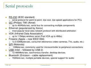
Introduction • Communication interfaces: • For exchanging information with another IC or external devices, e.g., I2C, RS-232, USB, Ethernet ... • Serial communication: • A single bit is transferred at a time • Synchronous: a clock signal is sent along with the data; the device that generates the clock is called the master and other devices are slaves • Asynchronous: no clock transmitted, fewer wires • Parallel communication: • Multiple bits are transferred at a time
Asynchronous Serial Communication • A simple and universal communication scheme • Can be managed in hardware by a peripheral called a universal asynchronous receiver/transmitter (UART), which is built into many microcontrollers • Even if UART is not available, it can be emulated easily with a timer assisted by software • Features: • Usually require only a single wire for each transmission direction plus a common ground wire • Most general-purpose connections are full duplex, i.e. data can be sent simultaneously in both directions • Often connect two end devices (not a bus)
Asynchronous Serial Communication • Serial comm. without carrying clock signal • How to synchronize the transmissions of the two ends which run based on independent clocks? • Use absolute (real) time • Transmit short data (e.g. one byte) at a time, assuming the two clocks run at the same rate during that short period of time
Data Format for Asyn Transmission • Data are sent in short frames, each of which typically contains a single byte • The line idles high and each frame contains: • one low start bit (ST) • eight data bits, usually LSB first • one high stop bit (SP) 8-N-1 format: 8-bit data, no parity bit, 1 stop bit
Transmission Speed • Baud rate: • # of signal changes per second, e.g., 9600 baud • In RS-232, each signal change represents one bit, so baud rate and bits per second are equal • Since each 8 bits of data are accompanied by a start and stop bit, max. data rate is only 8/10 of baud rate • How close must the two ends run their clocks? • The final sample is taken 9.5 bit periods after the initial falling edge and must lie within the stop bit • The permissible error is therefore about ±0.5 bit period in 9.5 periods or ±5% • There may be errors in both receiver and transmitter, so each should be accurate to within about ±2%
RS-232 • Standard for asynchronous serial communication • Originally for connecting equipment such as teletype (data terminal equipment, DTE) to modem (data communication equipment, DCE) • Old version, RS-232-C, published in 1969 • Current version, ANSI/TIA/EIA-232-F, maintained by the Telecommunication Industry Association (EIA) • Main features: • Connection must be less than 50 feet • Voltage level: 1 (-3~-15V), 0 (+3~+15V) • Region between ±3 V does not correspond to valid data • MSP430’s voltage is less than 3V use transceiver Falling edge means 0 1
UART: Universal Asynchronous Receiver Transmitter Takes parallel data and transmits serially Receives serial data and converts to parallel Sending UART 1 0 0 1 1 0 1 1 1 0 0 1 1 0 1 1 Serial Transmission Using UARTs embedded device 0 1 1 1 0 1 1 0 Receiving UART start bit end bit data
Outline • Introduction to communication interfaces • Asynchronous serial communication • Asynchronous serial communication in MSP430 using software and Timer_A • Asynchronous serial communication supports in MSP430
Software UART Using Timer_A • Software UART on MSP430 using Timer_A without relying on special UART hardware • e.g., MSP430g2331 does not have hardware UART • Use software to control Timer_A to handle serial IO directly and process the sampled input or set up the next bit for output in an ISR
How to Do? • General procedure for receive (RX) • Hardware detect falling edge on serial input, which indicates a start bit; start timer for 0.5 bit period • On timer interrupt, sample the serial input to confirm whether a valid start bit is received; if so, set timer for a further complete bit period • On timer interrupt, sample the input to read the first bit (LSB); set timer for another bit period • Repeat this until all 8 bits have been received • Wait a further bit period and check that the input is high as expected for the stop bit. A framing error occurs if this bit is low. Transmission (TX) similar!
How to Leverage Timer_A? • For receive: • Use capture mode of a capture/compare block: When an event occurs on an input to the block, the register TACCRx will store the “time”, i.e., the value in TAR, of that event • The inputvalue will belatched inSCCI bit RXD pin
How to Leverage Timer_A? • For transmission: • Use output circuit of Timer_A • e.g., if OUTMOD=0, output of the block is controlled directly byOUT bit in TACCTLx, as if the pin is used for normal, digital output but operated via Timer_A TXD pin
General Procedure by Timer_A • Between transmissions, the channel waits in the Capture mode for a falling edge on its input. • When a falling edge is detected, TACCRx will capture the count in TAR and an interrupt is requested. The channel is switched to the Compare mode, and TACCRx will be set to fire an interrupt after 1.5 of the length of a bit in time from now. • The next interrupt occurs and it should be in the middle of the LSB. SCCI contains the value of LSB. ISR saves it. Next compare event is set up to occur after a further bit length. • The above procedure is repeated until all 8 bits of data have been received.
ForLaunchPad LaunchPad thinks thatit has physical RS232links with PC, whilePC also thinks it hasphysical COM port(RS232) to LaunchPad
Outline • Introduction to communication interfaces • Asynchronous serial communication • Asynchronous serial communication in MSP430 using software and Timer_A • Asynchronous serial communication supports in MSP430
Comm. Peripherals in MSP430 • Universal Serial Interface (USI): • A lightweight module handles only synchronous comm.: SPI and I2C • Included in MSP430G2331 • Universal Serial Comm. Interface (USCI): • Handle almost all aspects of the communication • Asynchronous channel, USCI_A: act as a universal asynchronous receiver/transmitter (UART) to support the usual RS-232 communication • Synchronous channel, USCI_B: handle both SPI and I²C as either master or slave • Included in MSP430G2553