Download
1 / 59
620 likes | 848 Views
Robot Arms, Hands: Kinematics. With slides from Renata Melamud. Kinematics studies the motion of bodies. What a robot arm and hand can do. Martin 1992-’97 PhD work. What a robot arm and hand can do. Camilo 2011-? PhD work. Robotics field. 6 Million mobile robots

E N D
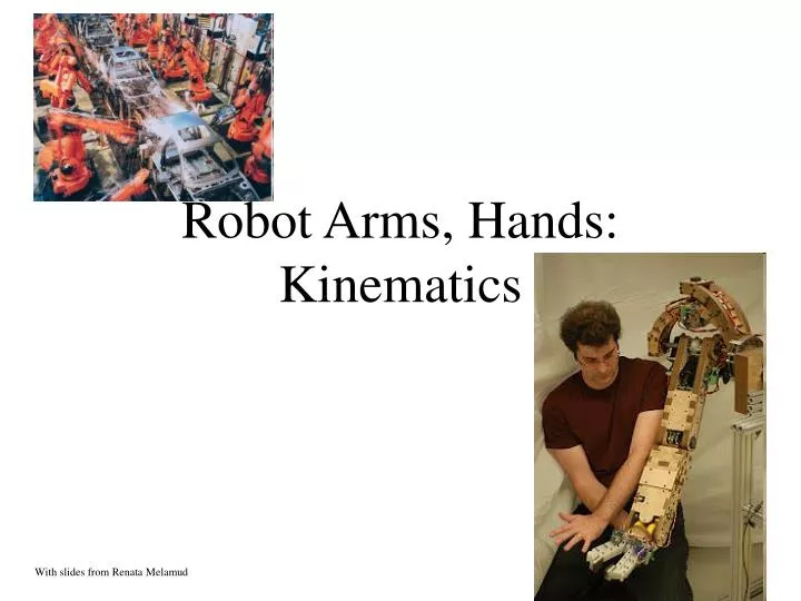
Robot Arms, Hands:Kinematics With slides from Renata Melamud
What a robot arm and hand can do • Martin 1992-’97 PhD work
What a robot arm and hand can do • Camilo 2011-? PhD work
Robotics field . . • 6 Million mobile robots • From $100 roomba to $millions Mars rovers • 1 million robot arms • Usually $20,000-100,000, some millions • Value of industrial robotics: $25 billion • Arms crucial for these industries: • Automotive (Welding, painting, some assembly) • Electronics (Placing tiny components on PCB) • General: Pack boxes, move parts from conveyor to machines http://www.youtube.com/watch?v=DG6A1Bsi-lg
An classic arm - The PUMA 560 2 3 4 1 There are two more joints on the end effector (the gripper) The PUMA 560 hasSIXrevolute joints A revolute joint has ONE degree of freedom ( 1 DOF) that is defined by its angle
An modern arm - The Barrett WAM • The WAM has SEVEN revolute joints. • Similar motion (Kinematics) to human
UA Robotics Lab platform2 arm mobile manipulator • 2 WAM arms, steel cable transmission and drive • Segway mobile platform • 2x Quad core computer platform. • Battery powered, 4h run time.
Robotics challenges Manipulation ‘11-14 Navigation ‘05 Humanoids ’12-
Build or buy? Lego Lynxmotion • Off the shelf kits: • Build your own:
Mathematical modeling Strategy: • Model each joint separately • Combine joints and linkage lengths Robot Abstract model http://www.societyofrobots.com/robot_arm_tutorial.shtml
Other basic joints Revolute Joint 1 DOF ( Variable - ) Prismatic Joint 1 DOF (linear) (Variables - d) Spherical Joint 3 DOF ( Variables - 1, 2, 3)
Successive translation and rotation % robocop Simulates a 3 joint robot function Jpos = robocop(theta1,theta2,theta3,L1,L2,L3,P0) Rxy1 = [cos(theta1) sin(theta1) 0 -sin(theta1) cos(theta1) 0 0 0 1]; Rxz2 = [cos(theta2) 0 sin(theta2) 0 1 0 -sin(theta2) 0 cos(theta2)]; Rxz3 = [cos(theta3) 0 sin(theta3) 0 1 0 -sin(theta3) 0 cos(theta3)]; P1 = P0 + Rxy1*[L1 0 0]'; P2 = P1 + Rxy1*Rxz2*[L2 0 0]'; P3 = P2 + Rxy1*Rxz2*Rxz3*[L3 0 0]'; Jpos = [P0 P1 P2 P3]; ExampleMatlab robot
Robot Base frame End-effector frame Object Problem: Lots of coordinate frames to calibrate
Camera Center of projection Different models Robot Base frame End-effector frame Object Problem: Lots of coordinate frames to calibrate
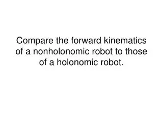
We are interested in two kinematics topics Forward Kinematics (angles to position) What you are given: The length of each link The angle of each joint What you can find: The position of any point (i.e. it’s (x, y, z) coordinates Inverse Kinematics (position to angles) What you are given: The length of each link The position of some point on the robot What you can find: The angles of each joint needed to obtain that position
Change Coordinate Frame Y1 O (VN,VO) Y0 N VNO VXY X1 P Translation along P followed by rotation by X0 (Note : Px, Py are relative to the original coordinate frame. Translation followed by rotation is different than rotation followed by translation.) In other words, knowing the coordinates of a point (VN,VO) in some coordinate frame (NO) you can find the position of that point relative to your original coordinate frame (X0Y0).
HOMOGENEOUS REPRESENTATION Putting it all into a Matrix What we found by doing a translation and a rotation Padding with 0’s and 1’s Simplifying into a matrix form Homogenous Matrix for a Translation in XY plane, followed by a Rotation around the z-axis
Rotation Matrices in 3D – OK,lets return from homogenous repn Rotation around the Z-Axis Rotation around the Y-Axis Rotation around the X-Axis
Y P X Z Homogeneous Matrices in 3D H is a 4x4 matrix that can describe a translation, rotation, or both in one matrix O N A Translation without rotation Y O N X Rotation part: Could be rotation around z-axis, x-axis, y-axis or a combination of the three. Z Rotation without translation A
Homogeneous Continued…. The (n,o,a) position of a point relative to the current coordinate frame you are in. The rotation and translation part can be combined into a single homogeneous matrix IF and ONLY IF both are relative to the same coordinate frame.
Finding the Homogeneous Matrix EX. J Y N I T P X K A O Z Point relative to the I-J-K frame Point relative to the N-O-A frame Point relative to the X-Y-Z frame
J Y N I T P X K A O Z Substituting for
Product of the two matrices Notice that H can also be written as: H = (Translation relative to the XYZ frame) * (Rotation relative to the XYZ frame) * (Translation relative to the IJK frame) * (Rotation relative to the IJK frame)
J I K The Homogeneous Matrix is a concatenation of numerous translations and rotations Y N T P X A O Z One more variation on finding H: H = (Rotate so that the X-axis is aligned with T) * ( Translate along the new t-axis by || T || (magnitude of T)) * ( Rotate so that the t-axis is aligned with P) * ( Translate along the p-axis by || P || ) * ( Rotate so that the p-axis is aligned with the O-axis) This method might seem a bit confusing, but it’s actually an easier way to solve our problem given the information we have. Here is an example…
The Situation: You have a robotic arm that starts out aligned with the xo-axis. You tell the first link to move by 1 and the second link to move by 2. The Quest: What is the position of the end of the robotic arm? Solution: 1. Geometric Approach This might be the easiest solution for the simple situation. However, notice that the angles are measured relative to the direction of the previous link. (The first link is the exception. The angle is measured relative to it’s initial position.) For robots with more links and whose arm extends into 3 dimensions the geometry gets much more tedious. 2. Algebraic Approach Involves coordinate transformations.
Example Problem: You are have a three link arm that starts out aligned in the x-axis. Each link has lengths l1, l2, l3, respectively. You tell the first one to move by 1, and so on as the diagram suggests. Find the Homogeneous matrix to get the position of the yellow dot in the X0Y0 frame. Y3 3 2 3 X3 Y2 2 H = Rz(1) * Tx1(l1) * Rz(2) * Tx2(l2) * Rz(3) i.e. Rotating by 1will put you in the X1Y1frame. Translate in the along the X1 axis by l1. Rotating by 2will put you in the X2Y2frame. and so on until you are in the X3Y3frame. The position of the yellow dot relative to the X3Y3frameis (l1, 0). Multiplying H by that position vector will give you the coordinates of the yellow point relative the the X0Y0frame. X2 Y0 1 X1 1 Y1 X0
Slight variation on the last solution: Make the yellow dot the origin of a new coordinate X4Y4 frame Y3 Y4 3 2 3 X3 Y2 2 X2 X4 H = Rz(1) * Tx1(l1) * Rz(2) * Tx2(l2) * Rz(3) * Tx3(l3) This takes you from the X0Y0 frame to the X4Y4 frame. The position of the yellow dot relative to the X4Y4 frame is (0,0). Y0 1 X1 1 Y1 X0 Notice that multiplying by the (0,0,0,1) vector will equal the last column of the H matrix.
More on Forward Kinematics… Denavit - Hartenberg Parameters
Denavit-Hartenberg Notation Z(i - 1) Y(i -1) Y i Z i X i a i a(i - 1 ) d i X(i -1) i ( i - 1) IDEA: Each joint is assigned a coordinate frame. Using the Denavit-Hartenberg notation, you need 4 parameters to describe how a frame (i) relates to a previous frame ( i -1 ). THE PARAMETERS/VARIABLES: , a , d,
The Parameters You can align the two axis just using the 4 parameters Z(i - 1) Y(i -1) Y i Z i X i a i a(i - 1 ) di X(i -1) i ( i - 1) 1) a(i-1) Technical Definition: a(i-1) is the length of theperpendicular between the joint axes. The joint axes is the axes around which revolution takes place which are the Z(i-1) and Z(i) axes. These two axes can be viewed as lines in space. The common perpendicular is the shortest line between the two axis-lines and is perpendicular to both axis-lines.
Z(i - 1) Y(i -1) Y i Z i X i a i a(i - 1 ) di X(i -1) i ( i - 1) a(i-1) cont... Visual Approach - “A way to visualize the link parameter a(i-1) is to imagine an expanding cylinder whose axis is the Z(i-1) axis - when the cylinder just touches the joint axis i the radius of the cylinder is equal to a(i-1).” (Manipulator Kinematics) It’s Usually on the Diagram Approach - If the diagram already specifies the various coordinate frames, then the common perpendicular is usually the X(i-1) axis. So a(i-1) is just the displacement along the X(i-1) to move from the (i-1) frame to the i frame. If the link is prismatic, then a(i-1) is a variable, not a parameter.
Z(i - 1) Y(i -1) Y i Z i X i a i a(i - 1 ) di X(i -1) i ( i - 1) 2) (i-1) Technical Definition: Amount of rotation around the common perpendicular so that the joint axes are parallel. i.e. How much you have to rotate around the X(i-1) axis so that the Z(i-1) is pointing in the same direction as the Zi axis. Positive rotation follows the right hand rule. 3) d(i-1) Technical Definition: The displacement along the Zi axis needed to align the a(i-1) common perpendicular to the aicommon perpendicular. In other words, displacement along the Zi to align the X(i-1) and Xi axes. 4) i Amount of rotation around the Zi axis needed to align theX(i-1) axis with the Xi axis.
Z(i - 1) Y(i -1) Y i Z i X i a i a(i - 1 ) di X(i -1) i ( i - 1) The Denavit-Hartenberg Matrix Just like the Homogeneous Matrix, the Denavit-Hartenberg Matrix is a transformation matrix from one coordinate frame to the next. Using a series of D-H Matrix multiplications and the D-H Parameter table, the final result is a transformation matrix from some frame to your initial frame. Put the transformation here
Y2 Z2 Z1 Z0 X2 d2 X0 X1 Y0 Y1 a0 a1 3 Revolute Joints Denavit-Hartenberg Link Parameter Table Notice that the table has two uses: 1) To describe the robot with its variables and parameters. 2) To describe some state of the robot by having a numerical values for the variables.
Y2 Z2 Z1 Z0 X2 d2 X0 X1 Y0 Y1 a0 a1 Note: T is the D-H matrix with (i-1) = 0 and i = 1.
This is just a rotation around the Z0 axis This is a translation by a1 and then d2 followed by a rotation around the X2 and Z2 axis This is a translation by a0 followed by a rotation around the Z1 axis
I n v e r s e K i n e m a t i c s From Position to Angles
A Simple Example Revolute and Prismatic Joints Combined Finding : More Specifically: (x , y) arctan2() specifies that it’s in the first quadrant Y S 1 Finding S: X
l2 l1 Inverse Kinematics of a Two Link Manipulator (x , y) Given:l1, l2 ,x , y Find:1, 2 Redundancy: A unique solution to this problem does not exist. Notice, that using the “givens” two solutions are possible. Sometimes no solution is possible. 2 l2 l1 1 (x , y) l2 l1
The Geometric Solution (x , y) Using the Law of Cosines: l2 2 l1 1 Using the Law of Cosines: Redundant since 2 could be in the first or fourth quadrant. Redundancy caused since 2 has two possible values
The Algebraic Solution (x , y) l2 2 l1 1 Only Unknown
The Numeric solution Y3 Y4 r3 2 3 X3 Y2 r2 X2 X4 We model forward kinematics as H = Ry(r1) * Tx1(l1) * Rz(r2) * Tx2(l2) * Rz(r3) * Tx3(l3) Now given desired Cartesian position [X,Y,Z] solve numerically for the corresponding joint angles [r1 r2 r3] : Y0 1 X1 r1 Y1 X0
The Numeric solution: How to solve?Newton’s Metod Y3 Y4 r3 2 3 X3 Y2 r2 X2 X4 Function: Jacobian J = matrix of partial derivatives: Newton’s method: Guess initial joint angles r Iterate J*dr = W-f( r ) r = r+dr If guess is close enough r converges to solution. Otherwise may diverge. Y0 1 X1 r1 Y1 X0
Newton’s Metod: Convergence issues X X Use a start position with known W and r (e.g. Wi = [0, l1 +l2 +l3 , 0, 1]^T for r = 0) Let next Wk close to this initial. Use r0 as initial guess for r1 Iterate J*dr = Wk-f( r ) r = r+dr r guess is close so r converges to solution. Y Y 3 3 r3 r3 2 2 r2 r2 1 1 r1 r1
Newton’s Metod: Convergence issues • To make a large movement, divide the total distance from (known) initial Wi to the new final Wf into small steps Wk • e.g. on a line • Try this in lab! X Y 3 r3 Y4 r3 2 2 3 X3 X4 r2 1 1 Y1 r1
Resolved rate control • Here instead of computing an inverse kinematics solution then move the robot to that point, we actually move the robot dr for every iteration in newtons method. • Let dr 0, then we can view this as velocity control:
Conclusion • Forward kinematics can be tedious for multilink arms • Inverse kinematics can be solved algebraically or numerically. The latter is more common for complex arms or vision-guided control (later) • Limitations: We avoided details of the various angular representations (Euler, quarternion or exponentials) and their detailed use in Kinematics. (this typically takes several weeks of course time in engineering courses)
Quick Math Review Dot Product: Geometric Representation: Matrix Representation: Unit Vector Vector in the direction of a chosen vector but whose magnitude is 1.