Download
1 / 6
60 likes | 66 Views
How to use Network Analyzer to measure resonant frequency of HF (13.56MHz) passive transponders. Josh Wyatt Texas Instruments Embedded RF Applications/Systems 02/16/2011. Method Steps. Fabricate transmit/pickup coil fixture Slide 3

E N D
How to use Network Analyzer to measure resonant frequency of HF (13.56MHz) passive transponders Josh Wyatt Texas Instruments Embedded RF Applications/Systems 02/16/2011
Method Steps • Fabricate transmit/pickup coil fixture Slide 3 • Frequency Settings, Calibration and Display Settings for Vector Network Analyzer (VNA) Slide 4 • Measure transponder fRES and BW Slide 5 • Calculate XL and L of tag from resonance measurement and known tag IC input capacitance Slide 6
Transmit/Pickup Coil • Example is made from 24mm bobbin, 22mm, 10mm bobbin, some SMA coaxial connectors and cable. • This can be used with VNA and also spectrum analyzer with tracking generator. • Dimensions are not super critical, this is just one example that does work. • Single turn coil to Port 1(blue wire) • Two turn coil to Port 2 (red wire) Dimensioned Drawing of Example Actual Example
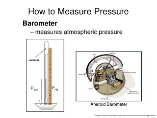
VNA Settings & Calibration • Set VNA for: • 13.56MHz center frequency • 5MHz span • Calibrate for 2 port Transmission Measurement (just need thru) • Attach Transmit/Pickup Coil Assembly • Set Scale for: 3dB/div • Reference Value = -25dB • Reference Position = 10 divisions • Log Mag View Example Measurement with properly tuned tag fC = 13.72MHz, BW = 683kHz, Q = 20
Resonant Frequency and Bandwidth Measurement • Put Tag on pickup coil fixture • Activate 3 markers • Marker 1 = fCENTER • Marker 2 = f1 • Marker 3 = f2 • BW = f2 - f1 • Use bandwidth captured to calculate Q value, where: Kiloway based tag being measured on VNA fixture fC = 14.4MHz, BW = 610kHz, Q = 23.6 FCI based tag on fixture
Calculate L, then XL based on measured value • Using transponder resonant frequency measurement and known input capacitance of transponder IC, L then XL can be calculated without having to break the tag IC/coil connection to measure directly. • Using known TI input capacitance (23.5pF) and measurement previously shown on slide 4, calculation examples are below. Complex impedance would be: ~ 1+ j488 to 1+j493