Download
1 / 26
280 likes | 305 Views
58. HORN, WIPER, AND BLOWER MOTOR CIRCUITS. Figure 58-1 Two horns are used on this vehicle. Many vehicles use only one horn, often hidden underneath the vehicle. Figure 58-2 A typical horn circuit. Note that the horn button completes the ground circuit for the relay.

E N D
58 HORN, WIPER, AND BLOWER MOTOR CIRCUITS
Figure 58-1 Two horns are used on this vehicle. Many vehicles use only one horn, often hidden underneath the vehicle.
Figure 58-2 A typical horn circuit. Note that the horn button completes the ground circuit for the relay.
Figure 58-3 Horns typically mount to the radiator core support or bracket at the front of the vehicle.
Figure 58-4 A circuit diagram is necessary to troubleshoot a windshield wiper problem.
Figure 58-5 The motor and linkage bolt to the body and connect to the switch with a wiring harness.
Figure 58-6 A typical wiper motor with the housing cover removed. The motor itself has a worm gear on the shaft that turns the small intermediate gear, which then rotates the gear and tube assembly, which rotates the crank arm (not shown) that connects to the wiper linkage.
Figure 58-7 A wiring diagram of a two-speed windshield wiper circuit using a three-brush, two-speed motor. The dashed line for the multifunction lever indicates that the circuit shown is only part of the total function of the steering column lever.
Figure 58-8 A wiring diagram of a three-speed windshield wiper circuit using a two-brush motor, but both a series-wound and a shunt field coil.
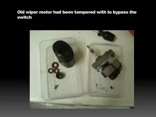
FREQUENTLY ASKED QUESTION: How Do Wipers Park? Some vehicles have wiper arms that park lower than the normal operating position so that they are hidden below the hood when not in operation. This is called a depressed park position. When the wiper motor is turned off, the park switch allows the motor to continue to turn until the wiper arms reach the bottom edge of the windshield. Then the park switch reverses the current flow through the wiper motor, which makes a partial revolution in the opposite direction. The wiper linkage pulls the wiper arms down below the level of the hood and the park switch is opened, stopping the wiper motor.
Figure 58-9 A variable pulse rate windshield wiper circuit. Notice that the wiring travels from the passenger compartment through pass-through grommets to the underhood area.
Figure 58-11 The wiper motor and linkage mount under the cowl panel on many vehicles.
Figure 58-12 A single wiper arm mounts directly to the motor on most rear wiper applications.
Figure 58-13 Circuit diagram of a rheostat-controlled, electronically timed interval wiper.
TECH TIP: Use a Scan Tool to Check Accessories Most vehicles built since 2000 can have the lighting and accessory circuits checked using a scan tool. A technician can use the following: • Factory scan tool, such as: • Tech 2 or Multiple Diagnostic Interface (MDI) (General Motors vehicle) • DRB III or Star Scan or Star Mobile or WiTech (Chrysler- Jeep vehicles) • New Generation Star or IDS (Ford) • Honda Diagnostic System (HDS) • TIS Tech Stream (Toyota/Lexus) • Enhanced aftermarket scan tool that has body bidirectional control capability, including: • Snap-on Modis, Solus, or Verus • OTC Genisys • Autoengenuity Using a bidirectional scan tool allows the technician to command the operation of electrical accessories such as windows, lights, and wipers. If the circuit operates correctly when commanded by the scan tool and does not function using the switche(s), follow service information instructions to diagnose the switch circuits.
Figure 58-14 Disconnect the hose at the pump and operate the switch to check a washer pump.
Figure 58-15 Washer pumps usually install into the reservoir and are held in place with a retaining ring.
Figure 58-16 A typical rain sensing module located on the inside of the windshield near the inside rearview mirror.
Figure 58-17 The electronics in the rain sense wiper module can detect the presence of rain drops under various lighting conditions.
Figure 58-18 A squirrel cage blower motor. A replacement blower motor usually does not come equipped with the squirrel cage blower, so it has to be switched from the old motor.
Figure 58-19 A typical blower motor circuit with four speeds. The three lowest fan speeds (low, medium-low, and medium-high) use the blower motor resistors to drop the voltage to the motor and reduce current to the motor. On high, the resistors are bypassed. The “high” position on the fan switch energizes a relay, which supplies the current for the blower on high through a fusible link.
Figure 58-20 A typical blower motor resistor pack used to control blower motor speed. Some blower motor resistors are flat and look like a credit card and are called “credit card resistors”.
Figure 58-21 A brushless DC motor that uses the body computer to control the speed. (Courtesy of Sammy’s Auto Service, Inc.)
TECH TIP: The 20 Ampere Fuse Test Most blower motors operate at about 12 A on high speed. If the bushings (bearings) on the armature of the motor become worn or dry, the motor turns more slowly. Because a motor also produces counterelectromotive force (CEMF) as it spins, a slower-turning motor will actually draw more amperes than a fast-spinning motor. If a blower motor draws too many amperes, the resistors or the electronic circuit controlling the blower motor can fail. Testing the actual current draw of the motor is sometimes difficult because the amperage often exceeds the permissible amount for most digital meters. One test recommended by General Motors Co. is to unplug the power lead to the motor (retain the ground on the motor) and use a fused jumper lead with one end connected to the battery’s positive terminal and the other end to the motor terminal. Use a 20 A fuse in the test lead, and operate the motor for several minutes. If the blower motor is drawing more than 20 A, the fuse will blow. Some experts recommend using a 15 A fuse. If the 15 A fuse blows and the 20 A fuse does not, then you know the approximate blower motor current draw.
Figure 58-22 Using a mini AC/DC clamp-on multimeter to measure the current draw of a blower motor.