Download
1 / 11
120 likes | 292 Views
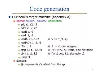
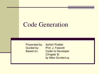
Target code Generation. Made by – Siddharth Rakesh 11CS30036 Date – 12/11/2013. Instruction set. The format is : op dst,src Load dst , src Store dst , src Arithmetic/Logical operation: - OP dst , src1, src2 - Ex – ADD R0, R1, R2 - ADD R0, R1, M

E N D
Target code Generation Made by – Siddharth Rakesh 11CS30036 Date – 12/11/2013
Instruction set The format is : op dst,src • Load dst, src • Store dst, src • Arithmetic/Logical operation: - OP dst, src1, src2 - Ex – ADD R0, R1, R2 - ADD R0, R1, M • Unconditional Branch - BRN L • Conditional Branch - B x L - BGTZ x L
Addressing modes: • Immediate – We allow an immediate constant addressing mode. The constant is prefixed by #. • Register – A memory location can be an integer indexed by a register. • Indirect – We allow 2 indirect addressing modes: *r means the memory location found in the location represented by the contents of register r and *100(r) means the memory location found in the location obtained by adding 100 to the contents of r. • Indexed – A location can also be an indexed address of the form a(r), where a is a variable and r is a register.
Challenges of Code Generation • Instruction selectionEach 3 – address code statement maps to the target code.Ex – x = y + z Load R1, y Add R1, R1, z Store x, R1 • Register Allocationa. We have v variables, we select n variables and store them in n registers.b. Register assignment – specific register variable xc. Optimality of target code – Metric – i. Number of memory accesses required ii. Length of instruction
Rule of assignment of cost –1. + 1 for any instruction.2. Additional cost of 1 for memory access. • Ex – Add R0, R1, R2 Cost = 1 - Add R0, R1, M Cost = 2 (because of memory access)
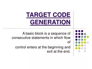
Conversion from intermediate code to m/c code • Split the Intermediate code into basic blocks.Block: A sequence of code instructions executed together. • Ex – a = b + c c = d + f block goto L1 block breaks here and jumps L1: ……
Control will enter the first block with the first instruction. • There should not be any jump in the middle of the block. • Control can leave this block by executing the last instruction. We must identify the first instruction (leaders) of all basic blocks.
Steps to identify the leaders • 1st instruction of the 3 address code is a leader. • All labels corresponding to the target statements are leaders. • Statements following GOTO are leaders. A Block may thus be defined as ‘all instructions following a leader until next leader comes’.
Example : • loc = -1 leader • i = 0 • L1 : if i < 10 goto L2 leader • goto L5 leader • t1 = 2 * I leader • t2 = A[t1] • If t2 = x goto L3 leader • goto L4 leader • L3 : loc = ileader • L4 : t3 = i + 1 leader • i = t3 • goto L1 • L5 : leader
Flow graph • The flow graph depicts the flow of control through the body of the graph. • Each node will be a basic block. • Arcs from a node i j signify the transfer of control from block i to block j.
Line numbers corresponding to blocks B1 1,2 B2 Control flow graph based on previous example: 3 B3 4 B4 5,6,7 B5 8 B6 9 B7 10,11,12 B8 13