Download
1 / 1
10 likes | 136 Views
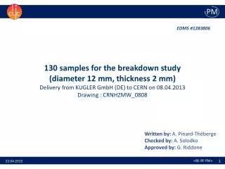
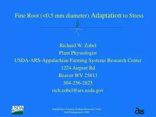
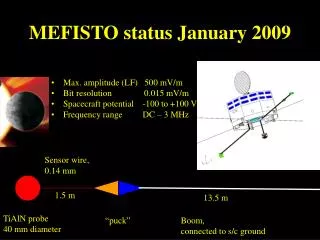
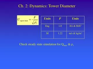
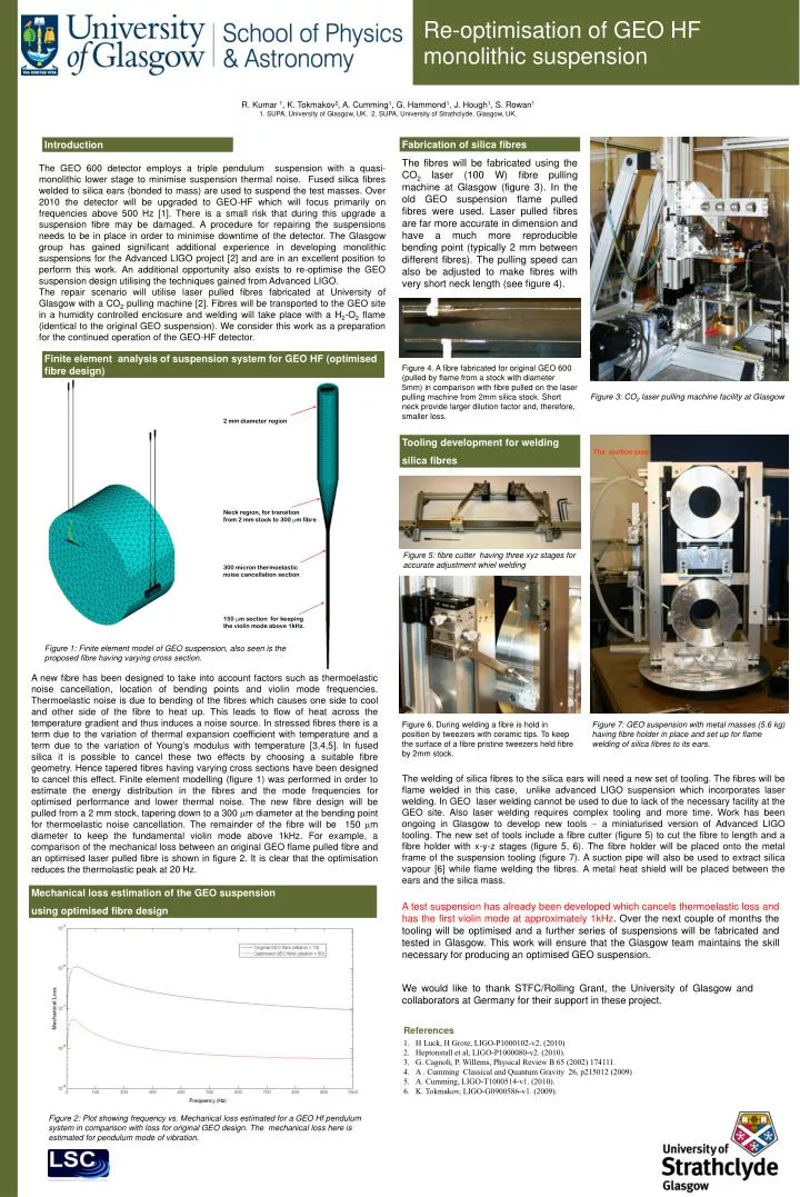
2 mm diameter region. The suction pipe. Neck region, for transition from 2 mm stock to 300 m fibre. 300 micron thermoelastic noise cancellation section. 150 m section for keeping the violin mode above 1kHz.

E N D
2 mm diameter region The suction pipe Neck region, for transition from 2 mm stock to 300 m fibre 300 micron thermoelastic noise cancellation section 150 m section for keeping the violin mode above 1kHz. Figure 1: Finite element model of GEO suspension, also seen is the proposed fibre having varying cross section. Re-optimisation of GEO HF monolithic suspension R. Kumar 1, K. Tokmakov2, A. Cumming1, G. Hammond1, J. Hough1, S. Rowan1 1. SUPA, University of Glasgow, UK, 2. SUPA, University of Strathclyde, Glasgow, UK, Fabrication of silica fibres Introduction The fibres will be fabricated using the CO2 laser (100 W) fibre pulling machine at Glasgow (figure 3). In the old GEO suspension flame pulled fibres were used. Laser pulled fibres are far more accurate in dimension and have a much more reproducible bending point (typically 2 mm between different fibres). The pulling speed can also be adjusted to make fibres with very short neck length (see figure 4). The GEO 600 detector employs a triple pendulum suspension with a quasi-monolithic lower stage to minimise suspension thermal noise. Fused silica fibres welded to silica ears (bonded to mass) are used to suspend the test masses. Over 2010 the detector will be upgraded to GEO-HF which will focus primarily on frequencies above 500 Hz [1]. There is a small risk that during this upgrade a suspension fibre may be damaged. A procedure for repairing the suspensions needs to be in place in order to minimise downtime of the detector. The Glasgow group has gained significant additional experience in developing monolithic suspensions for the Advanced LIGO project [2] and are in an excellent position to perform this work. An additional opportunity also exists to re-optimise the GEO suspension design utilising the techniques gained from Advanced LIGO. The repair scenario will utilise laser pulled fibres fabricated at University of Glasgow with a CO2 pulling machine [2]. Fibres will be transported to the GEO site in a humidity controlled enclosure and welding will take place with a H2-O2 flame (identical to the original GEO suspension). We consider this work as a preparation for the continued operation of the GEO-HF detector. Finite element analysis of suspension system for GEO HF (optimised fibre design) Figure 4. A fibre fabricated for original GEO 600 (pulled by flame from a stock with diameter 5mm) in comparison with fibre pulled on the laser pulling machine from 2mm silica stock. Short neck provide larger dilution factor and, therefore, smaller loss. Figure 3: CO2 laser pulling machine facility at Glasgow Tooling development for welding silica fibres Figure 5: fibre cutter having three xyz stages for accurate adjustment whiel welding A new fibre has been designed to take into account factors such as thermoelastic noise cancellation, location of bending points and violin mode frequencies. Thermoelastic noise is due to bending of the fibres which causes one side to cool and other side of the fibre to heat up. This leads to flow of heat across the temperature gradient and thus induces a noise source. In stressed fibres there is a term due to the variation of thermal expansion coefficient with temperature and a term due to the variation of Young’s modulus with temperature [3,4,5]. In fused silica it is possible to cancel these two effects by choosing a suitable fibre geometry. Hence tapered fibres having varying cross sections have been designed to cancel this effect. Finite element modelling (figure 1) was performed in order to estimate the energy distribution in the fibres and the mode frequencies for optimised performance and lower thermal noise. The new fibre design will be pulled from a 2 mm stock, tapering down to a 300 m diameter at the bending point for thermoelastic noise cancellation. The remainder of the fibre will be 150 m diameter to keep the fundamental violin mode above 1kHz. For example, a comparison of the mechanical loss between an original GEO flame pulled fibre and an optimised laser pulled fibre is shown in figure 2. It is clear that the optimisation reduces the thermolastic peak at 20 Hz. Figure 6. During welding a fibre is hold in position by tweezers with ceramic tips. To keep the surface of a fibre pristine tweezers held fibre by 2mm stock. Figure 7: GEO suspension with metal masses (5.6 kg) having fibre holder in place and set up for flame welding of silica fibres to its ears. The welding of silica fibres to the silica ears will need a new set of tooling. The fibres will be flame welded in this case, unlike advanced LIGO suspension which incorporates laser welding. In GEO laser welding cannot be used to due to lack of the necessary facility at the GEO site. Also laser welding requires complex tooling and more time. Work has been ongoing in Glasgow to develop new tools aminiaturised version of Advanced LIGO tooling. The new set of tools include a fibre cutter (figure 5) to cut the fibre to length and a fibre holder with x-y-z stages (figure 5, 6). The fibre holder will be placed onto the metal frame of the suspension tooling (figure 7). A suction pipe will also be used to extract silica vapour [6] while flame welding the fibres. A metal heat shield will be placed between the ears and the silica mass. Mechanical loss estimation of the GEO suspension using optimised fibre design A test suspension has already been developed which cancels thermoelastic loss and has the first violin mode at approximately 1kHz. Over the next couple of months the tooling will be optimised and a further series of suspensions will be fabricated and tested in Glasgow. This work will ensure that the Glasgow team maintains the skill necessary for producing an optimised GEO suspension. We would like to thank STFC/Rolling Grant, the University of Glasgow and collaborators at Germany for their support in these project. • References • H Luck, H Grote, LIGO-P1000102-v2. (2010) • Heptonstall et al, LIGO-P1000080-v2. (2010). • G. Cagnoli, P. Willems, Physical Review B 65 (2002) 174111. • A . Cumming Classical and Quantum Gravity 26, p215012 (2009) • A. Cumming, LIGO-T1000514-v1. (2010). • K. Tokmakov, LIGO-G0900586-v1. (2009). Figure 2: Plot showing frequency vs. Mechanical loss estimated for a GEO Hf pendulum system in comparison with loss for original GEO design. The mechanical loss here is estimated for pendulum mode of vibration.