Download
1 / 103
1.05k likes | 1.07k Views
Air Cooled Inverter Chiller. Technical Training. Content. Product Lineup & Features Components Schematic diagram Inverter technology Control Algorithm Chiller Panel Controller Self diagnosis & Troubleshooting Installation. Technical Training. Product Lineup & Features.

E N D
Air Cooled InverterChiller TechnicalTraining AirCooledInverterChiller
Content • ProductLineup&Features • Components • Schematicdiagram • Invertertechnology • ControlAlgorithm • ChillerPanelController • Selfdiagnosis&Troubleshooting • Installation TechnicalTraining AirCooledInverterChiller
Product Lineup & Features TechnicalTraining AirCooledInverterChiller
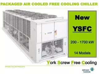
ProductLineup 5ACV100/135/210CR TechnicalTraining 5ACV55/75CR 5ACV30CR AirCooledInverterChiller
Capacity TechnicalTraining AirCooledInverterChiller
Features New Technology BPHE- True DualCircuits Conventional Back to Back CircuitsBPHE SecondaryCircuit Primary Circuit1 Primary Circuit2 TechnicalTraining 5ACV True Dual CircuitsBPHE Primary Circuit1 Primary Circuit2 AirCooledInverterChiller
Features InverterCompressor TechnicalTraining ConventionalSystem Inverter System AirCooledInverterChiller
Features Higher SeasonalEER TechnicalTraining Inverter is based on ESEER due to part loading(25%-50%-75%-100%). AirCooledInverterChiller
Features Elimination of WaterTank Inverter system provide constant Water Temperature band, or much lesser water temperature fluctuation. With this, water tank of mini chiller system can be eliminated ModularInstallation A network up to 50 chillers in a system is possible. Control on the operation of chillers will be done through the microprocessor controller. The external water piping connection can be made either from the left or right side of theunit. • SafetyProtection • High & Low PressureSwitches • Anti Freeze ProtectionSensor • Discharge TemperatureSensor • Over Pressure ReliefValve TechnicalTraining • Water Pressure DifferentialSwitch • Anti Freeze Heater onBPHE • Compressor, Water Pump Overload Protector AirCooledInverterChiller
Components TechnicalTraining AirCooledInverterChiller
Components Fanguards Coilguards Variable speed fan motors (100%, 70%& 50%) Heatexchangers with gold fin as standard True dual circuitsBPHE (Brazed plate heat exchanger) TechnicalTraining Waterpump Expansion tank (8L) Controlbox assembly AirCooledInverterChiller
Components High pressure switch (NC) 600 psi – open, 480psi –close. EXV(Electronics expansionvalve Low pressureswitch (NC) 18 psi – open, 28 psi –close. Chillerpanel controller Differential pressure switch 4 Wayvalve Over pressure relief valve Fixedspeed scroll compressor (R410A) Anti freeze heater on BPHE raining Pump OLP(overload protector) Variable speedscroll compressor (R410A) Technical T T Compressor OLP (overloadprotector) Variable drivesystem compartment Fixed drivesystem compartment AirCooledInverterChiller
Components Control boxassembly 3 phase rectifier bridgediode Uni- directional bridgediode PTCstarter (Positivetemperature coefficient) Fan capacitors IPMboard (Intelligent powermodule) Powerboard TechnicalTraining Capacitor board Mainboard PFCcapacitor (Power factorcorrection) EMIfilter Magnetic contactors AirCooledInverterChiller
Schematicdiagram TechnicalTraining AirCooledInverterChiller
Schematicdiagram Inverter chiller schematicdiagram Cond In Temp 1 (Condenser) CondOut Temp 1 (Def Comp1) 5ACV100CR Condenser Coil1 HP1 Filter Drier 4WV Disch Temp1 (Disch Comp 1) LP1 EXV Suct Temp (Suction) O/ATemp (OutdoorAir) BPHEIn Temp (BPHEIn) BPHE Out Temp (BPHEOut) LiqRvr Inv Comp Acc Pump EWT (WaterIn) LWT (WaterOut) TechnicalTraining BPHE FS Cooling CapTube HP2 Summary Pages- Screen3 4WV Disch Temp2 (Disch Comp 2) Checkvalve LP2 Display Menu- DefrostSensor Liq Rvr Filter Drier Display Menu- InverterChiller CondOut Temp2 Heating CapTube (Def Comp2) Std Comp DisplayMenu- Discharge Sensor Acc Condenser Coil2 Checkvalve AirCooledInverterChiller
Invertertechnology TechnicalTraining AirCooledInverterChiller
Invertertechnology What Inverter can do for us? Conventional System InverterSystem TechnicalTraining • Less Start&Stop • Fast Cooling/Heating • Smart Loading/Unloading • Better CompressorReliability AirCooledInverterChiller
Invertertechnology Brief Introduction on InverterTechnology Inverter basic structure TechnicalTraining Inverter control technology convert AC supply to DC and convert it back to AC. The frequency & voltage of each phase can be controlled and applied on asynchronous motor for variable loadcontrol. AirCooledInverterChiller
Invertertechnology Rectificationcircuit TechnicalTraining • To minimize emission effect (EMC) and raise immunity level (EMS), a LC filter isused. • PTC resistor acts to cushion start up current tocapacitor. • Diode bridge inverts AC toDC. AirCooledInverterChiller
Invertertechnology DCstage TechnicalTraining • PTC capacitor acts to restraint PF losses caused by fluctuation of DCvoltage. AirCooledInverterChiller
Invertertechnology Inversioncircuit TechnicalTraining • Inversion circuits consists of 6 IGBT. (Insulated Gate BipolarTransistor) • By controlling the linkages, different frequency and 3 phase AC voltage can be generated. • IPM (Intelligent Power Module) encased the inversion circuitry, error detection & protectionfeatures. AirCooledInverterChiller
Invertertechnology SPWM ( Sine pulse width modulation) TechnicalTraining By computing the on-off frequency and timing of IGBT, a series of output voltage pulse widths can be integrated to form a sine wave for application on VVVF. (Variable Voltage Variable Frequency) AirCooledInverterChiller
Invertertechnology VVVF (Variable voltage variablefrequency) • Every inverter chiller has its typical characteristic and VVVF (variable voltage variable frequency)curve. • To control Asynchronous motor, it is desirable to maintain magnetic flux for torquerequirement. • Excessive of magnetic flux will cause excitation and diminish theflux. • To maintain optimum flux, the voltage varies withfrequency. TechnicalTraining AirCooledInverterChiller
ControlAlgorithm TechnicalTraining AirCooledInverterChiller
ControlAlgorithm Variable Drive CompressorControl Cooling mode Start up condition: • Pump runs normally for 2 minutes* For example: Return water temp.= 14 to 16 °C Settemp = 12°C ΔT = 2 to 4°C • 2°C Twaterreturn–Tset4°C • No irreversible errors in variable drive and thesystems • Satisfy a delay of 3 minutes before restart# • Note : If fixed drive system starts first, the variable drive system should trail after 30sec. TechnicalTraining * Depends on Parameter P2 (flow switch alarm delay at pump start. Min 0s, max 199s, default 120s) # Depends on Parameter C2 (compressor min stop time. Min 0s, max 1990s, default 180s) AirCooledInverterChiller
ControlAlgorithm Cooling mode Cooling mode selected €water pump starts €Outdoor fan starts €variable drive compressorstarts Increase to rated frequency with the rate of1Hz/s RatedFreq. 5ACV100CR=75Hz 5ACV135CR=95Hz 55Hz Inverter compressor will start from 5Hz to 55Hz and maintain this frequency for 1 min. 5Hz t TechnicalTraining 3 min 5sec 1min Variable drivecomp ON OFF ON OFF Outdoorfan Outdoor fan will start 5 sec before compressorstart AirCooledInverterChiller
ControlAlgorithm • Cooling mode • Shut down condition: • Cooling mode terminates,OR • Variable drive system error occurs,OR TechnicalTraining –-2°C • T waterreturn Tset For example: Return water temp.=10°C Settemp =12°C ΔT =-2°C AirCooledInverterChiller
ControlAlgorithm Heating mode Start up condition: • Pump runs normally for 2 minutes* For example: Settemp = 40°C Return water temp.= 36 to 38 °C ΔT = 2 to4°C • 2°C4°C Tset - T waterreturn • No irreversible errors in variable drive and thesystems • Satisfy a delay of 3 minutes before restart# TechnicalTraining Note : If fixed drive system starts first, the variable drive system should trail after 30sec. * Depends on Parameter P2 (flow switch alarm delay at pump start. Min 0s, max 199s, default 120s) # Depends on Parameter C2 (compressor min stop time. Min 0s, max 1990s, default 180s) AirCooledInverterChiller
ControlAlgorithm Heating mode Heating mode selected €water pump starts €Variable drive4WV engages €Outdoor fan starts €compressorstarts Increase to rated frequency with the rate of1Hz/s RatedFreq. 5ACV100CR=65Hz 5ACV135CR=90Hz Inverter compressor will start from 5Hz to 45Hz and maintain this frequency for 1 min. 45Hz 5Hz t TechnicalTraining 3 min 10 sec 1min Variable drivecomp ON OFF ON OFF ON OFF Variable4WV Outdoorfan Outdoor fan will start 5 sec before compressorstart 5sec Variable drive 4WV start 10 sec before compressor start AirCooledInverterChiller
ControlAlgorithm Heating mode Shut down condition: • Heating mode terminates,OR • Variable drive system error occurs,OR TechnicalTraining -2°C For example: Settemp = 40°C Water return temp =42°C ΔT =-2°C • Tset - T waterreturn AirCooledInverterChiller
ControlAlgorithm • Fixed Drive CompressorControl • Cooling mode • Start up condition: • Pump runs normally for 2 minutes* For example: Water return temp =16°C Settemp =12°C ΔT = 4°C –>4°C • Twaterreturn Tset Fixed drive starts first followed by variabledrive • No irreversible errors in fixed drive and thesystems • Satisfy a delay of 3 minutes before restart# • Note : If variable drive system starts first, the fixed drive system will only start after the frequency of variable drive drops to50Hz. • * Depends on Parameter P2 (flow switch alarm delay at pump start. Min 0s, max 199s, default 120s) • # Depends on Parameter C2 (compressor min stop time. Min 0s, max 1990s, default180s) TechnicalTraining AirCooledInverterChiller
ControlAlgorithm Cooling mode Cooling mode selected €water pump starts €Outdoor fan starts €compressorstarts Fixed drive compressor starts ON Fixed drivecomp OFF 3min 5sec 1min ON Outdoorfan TechnicalTraining OFF Outdoor fan will start 5 sec before compressorstart Outdoor fan will stop after compressor has stopped for 1 min AirCooledInverterChiller
ControlAlgorithm • Cooling mode • Shut down condition: • Cooling mode terminates,OR • Fixed drive system error occurs,OR • 2°C and variable frequency drops pass20Hz TechnicalTraining • Tset - T waterreturn For example: Settemp = 12°C Water return temp = 10°C ΔT =2°C AirCooledInverterChiller
ControlAlgorithm • Heating mode Start up condition: • Pump runs normally for 2 minutes* For example: Settemp = 40°C Water return temp = 36°C ΔT =4°C >4°C • Tset - T waterreturn • No irreversible errors in fixed drive and thesystems • Satisfy a delay of 3 minutes before restart# • Note : If variable drive system starts first, the fixed drive system will start after the variable drive frequency drops to50Hz. • * Depends on Parameter P2 (flow switch alarm delay at pump start. Min 0s, max 199s, default 120s) • # Depends on Parameter C2 (compressor min stop time. Min 0s, max 1990s, default 180s) TechnicalTraining AirCooledInverterChiller
ControlAlgorithm Heating mode Heating mode selected €water pump starts €Fixed drive 4WV engages €Outdoor fan starts €compressorstarts Fixed drive compressor starts ON Fixed drivecomp OFF 1min 10sec 3min ON OFF TechnicalTraining 5sec Variable4WV ON OFF Outdoorfan Outdoor fan and 4WV will stop after compressor has stopped for 1min Fixed drive 4WV start 10 sec before compressorstart Outdoor fan will start 5 sec before compressorstart AirCooledInverterChiller
ControlAlgorithm • Heating mode • Shut down condition: • Heating mode terminates,OR • Fixed drive system error occurs,OR >2°C • T water return - Tset TechnicalTraining For example: Water return temp =42°C Settemp =40°C ΔT = 2°C AirCooledInverterChiller
ControlAlgorithm PumpControl Pump startup When starting the system, pump will run for 2 minutes * before proceeding to nextstep. * Depends on Parameter P2 (flow switch alarm delay at pump start. Min = 0s, Max = 199s, default =120s) Pump shutdown After both compressors shut down for 1 minute, pump shutsdown. TechnicalTraining AirCooledInverterChiller
ControlAlgorithm PumpControl System error When errors occur in the system and require system to shut down, the pump will shut down 1 minute after the system shuts down. If compressor is not running, the pump shuts downimmediately. Note : When changing operating mode or when temperature reaches setting, pump continues torun. TechnicalTraining AirCooledInverterChiller
ControlAlgorithm • Auxiliary heater control (Infoonly) • Start upconditions • System in heating modeAND • System no error alarmAND • After heating starts for 1 hourand Heating Noerror Running 1 hour ΔT>5°C Forexample: Settemp = 40°C Water return temp = 34°C ΔT =6°C T set – T water return >5°C The second time start up is not time–dependent. • Switch offconditions • System terminates heating modeOR • Wired handset withdraws auxiliary heating command,OR • System errors trigger alarm and require shut down,OR TechnicalTraining HeXating • When T set – T water return <2°C Error ΔT<2°C AirCooledInverterChiller
ControlAlgorithm • EXV control (Electronic expansion valve) • When system operates for the first time, EXV will operate to preset openings. • After system operates for 10 minutes, the EXV will preset to superheat regulation for variable drivesystem. TechnicalTraining AirCooledInverterChiller
ControlAlgorithm 4 way reversible valvecontrol Select heatingmode 4 WV engage 5sec Heatingstarts Stop heatingmode compressorstops 4 WV disengage 60sec • When selecting heating mode, 4 way valve will engage 5 seconds before heating startup. • When heating stops, 4 way valve will disengage 60 seconds after compressorstops. • Compressor crankcase heater control • Fixed drive compressor crankcase heater is driven by the fixed drive contactor(NC). • Variable drive compressor crankcase heater is driven by main board relay. • Crankcase heater will be ON whenever compressors are not in operation. TechnicalTraining AirCooledInverterChiller
ControlAlgorithm • Outdoor fancontrol • Control basic • Fixed drive and variable drive outdoor fan are independently controlled. • During start up, fan operates at fixed speed. During operation, fans operate at variablespeed. • There are 3 fan speeds in High, Medium and Low fanspeed. • The High fan speed is 680 RPM and 3800CFM for each fanmotor. • The ratio of fan speed is 100%, 70% and 50%respectively. TechnicalTraining AirCooledInverterChiller
ControlAlgorithm • Outdoor fancontrol • Fan control forCooling • Within 20 minutes of normal operation, when Te (Outdoor ambient temp.) 28°C,fan • operates at highest speed. • Within 20 minutes of normal operation, when Te (Outdoor ambient temp.) <28°C, fan operates at mediumfan. • After normal operation for 20 minutes, when 40°C < (Ta3, Tb2) < 48°C, the fan operates to variable speed (PI regulation). The lower the temperature the lower the speed. Ta3,Tb2 Ta3 = condenser outlet temp. (Variable drivesystem) High fanzone TechnicalTraining 48°C Constant fanspeed control zone PI controlzone T = condenser outlettemp. b2 (Fixed drivesystem) 40°C PI = programintelligent Te 28°C (High fan) Te < 28°C (Medfan) Low fanzone 20min AirCooledInverterChiller
ControlAlgorithm • Outdoor fancontrol • Fan control forHeating • When Te (Outdoor ambient temp.) < 10°C, fan operates at highestspeed. • When 10°C Te (Outdoor ambient temp.) 12°C, fan operates at mediumfan. • When Te (Outdoor ambient temp.) > 12°C, fan operates at variable speed to PI regulation. The higher the temperature the lower thespeed. Te Lowfan PIcontrol 12°C TechnicalTraining PI=programintelligent Constant fan speed control zone (medium fan) 10°C Constant fan speed controlzone Highfan (highfan) Highfan t AirCooledInverterChiller
ControlAlgorithm Outdoor fancontrol Fan operation duringdefrosting Defroststart Defrostend 70Hz Variable drivecomp 30Hz 30Hz Resumeheating mode Variable4WV TechnicalTraining Outdoorfan Fan stops 1 minute after the compressorstops. AirCooledInverterChiller
ControlAlgorithm • Anti freeze heater control • Anti freeze on/off control during systemstandby • Runs when system in standbymode • If Te (outdoor ambient temperature) 5°C and T water return 5°C, waterpump • runs 5 minutes every hour and antifreeze heater will run on and off together with the waterpump. • If T water return > 6°C water pump and antifreeze heater willstop. • If Te 2°C and T water return 2°C, system enters heating mode and returns to standby when T water return >30°C TechnicalTraining Run 5min/hr ON Waterpump Antifreezeheater ON °C System enters heatingmode 2 5 6 30 Water return temperature/Outdoor ambienttemperature AirCooledInverterChiller
ControlAlgorithm • Anti freeze heater control • Anti freeze duringcooling • When T water leaving 5°C, antifreeze heater will operate until T water leaving >7°C. • When T water leaving 3°C, alarm will setoffuntil T water leaving >5°C. TechnicalTraining Factory setting for antifreeze heater =5°C alarm set point =3°C Antifreezeheater ON °C Water leavingtemperature 3 5 7 Alarmon Alarmoff AirCooledInverterChiller
ControlAlgorithm • Defrostingcontrol • Automaticdefrosting • Shall satisfying the below automatic defrosting condition for 3 minutes: • Compressor operates continuously for at least the duration ofthe • defrostinginterval. • When Ta3 or Tb2 0°C *OR Ta3 = condenser outlet temp. (Variable drive system) Tb2 = condenser outlet temp. (Fixed drivesystem) • When T >18°C waterreturn * Depends on Parameter D1 (Start defrost temperature. Min -20°C, max 14°C, default 0°C) Note : Factory defrost interval depends on Parameter D4 (Defrost interval time). Intelligent defrost interval varies. Under Parameter defrost mode, Intelligent defrost is set as default under DISABLE mode. Factory standard defrost will be activated when the parameter is set toENABLE. Manual defrosting Manual defrosting can be carried out when Ta3 or Tb2 <7°C TechnicalTraining AirCooledInverterChiller
ControlAlgorithm • Defrostingcontrol • Defrosting process • Variable drive defrostingprocess • When defrosting conditions are met for variable drive, variable drive compressorstops • €outdoor fan stops €4WV disengages €variable drive starts defrost at90Hz. • When variable drive defrosting terminates, variable drive compressor stops €4WV engages €outdoor fan starts €variable drive compressor starts €Resumeheating • operation. • Defrost start Defrostend 90Hz Variable drivecomp TechnicalTraining Resumeheating mode 30Hz 30Hz Variable4WV ON OFF Outdoorfan ON OFF AirCooledInverterChiller
ControlAlgorithm • Defrostingcontrol • Defrosting process • Fixed drive defrostingprocess • When defrosting conditions are met for fixed drive, fixed drive compressor stops (15 sec) €outdoor fan stops (2 sec) €4WV disengages (10 sec) €fixed drive compressor startsdefrost • When fixed drive defrosting terminates, fixed drive compressor stops €outdoor fan starts at high speed for 30 sec €4 WV engages €Fixed drive compressor starts€ • Resume heatingoperation. • Defrost start Defrost end Resume heating mode ON OFF TechnicalTraining Fixed drivecomp 15sec 10sec 10sec ON OFF Outdoorfan 2sec ON OFF 4WV 2sec 2sec AirCooledInverterChiller