Download
1 / 13
130 likes | 135 Views
Multipacting simulation of MICE 201 MHz cavity. Tianhuan Luo. Multipacting.

E N D
Multipacting simulation of MICE 201 MHz cavity Tianhuan Luo
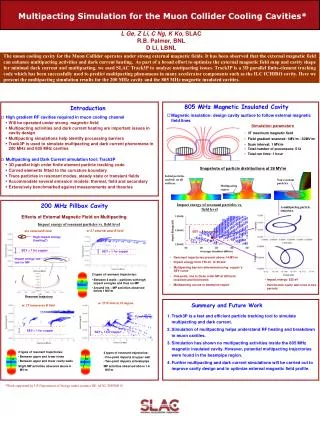
Multipacting • Multipacting: a phenomenon in RF device when secondary electron emission in resonance with an alternating electric field leads to exponential electron multiplication, possibly damaging and even destroying the RF device. • Secondary emission yield (SEY): the number of secondary electrons emitted per incident particle, strongly depends on the surface material and treatment. The secondary electron yield of thechnical materials and its variation with surface treatments, V.Baglin etc
SLAC ACE3P for Multipacting Simulation • Omega3P/S3P: calculate the EM field in the cavity with high resolution. • Track3P: launch electrons from the cavity surface, track their motion in RF field & external E/B field, and identify MP electrons with the SEY information input. • Bench marked with theory and experiment results ICHIRO Cavity Coaxial Waveguide MP in coaxial waveguide, which can be solved analytically. Multipacting simulation Using Parallel code Track3p, LixinGe
MICE 201 MHz Cavity • The model is derived from CAD drawing provided by Allan DeMello. • Include the extrusion ports, RF coupler, coaxial waveguide and curved Beryllium windows.
Omega3P simulation results B magnitude on the RF coupler surface Ez on the cavity surface f0=201.901 MHz, Q0=51656 Critical coupling is achieved with 15 degree coupling angle ( 90 degree corresponds to maximum coupling). Ez along the beam axis Ez along the cavity radial direction
External B field Map • The MICE Cavities are operated in a series of superconducting solenoids. Strong external magnetic field will change the MP significantly. • The external B field mapping is provided by Heng Pan, which includes all the coils in CC module, AFC module and SS module. Four different B field configurations for MICE operation. Four Cavities in a CC module B field plot at r=0 (center), r=0.6 m (RF coupler) and r=1.2 m (RF window).
MP results (1): coaxial waveguide Without external B With external B Impact Position: green without B field, magenta with B field.
MP results(2): cavity body Without external B With external B Impact Position: green without B field, magenta with B field.
MP results (3): RF coupler region Electron drift into waveguide Without external B Resonant electrons between strip and cavity wall With external B Impact Position: green without B field, magenta with B field.
A new RF coupler design • APEX originally used the same coupler as the old 201 MHz Mucoolprototype cavity, had multipacting (excess heating at waveguide)and needed external solenoid field to overcome MP barrier. Eventually the vacuum leaks at coupler water cooling loop. Observed severe heating and damage at coupler after opening the cavity. • New APEX coupler design: get rid of the strip, shorter the coaxial waveguide, thicken the cooling tube wall, and Ti-Ni the whole coupler and waveguide. Runs smoothly up to CW60 KW per coupler and keeps on running for days. No multipacting observed at coupler. New coupler model for simulation, based on Allan’s drawing CAD drawing of new APEX coupler
Simulation with new coupler f0=201.900 MHz, Q0=51675 Critical coupling is achieved with 16 degree coupling angle ( 90 degree corresponds to maximum coupling).
MP at new coupler region Without external B With external B Impact Position: green without B field, magenta with B field. The simulation shows just removing the strip doesn’t help to resolve the multipacting at the coupler, especially with external B field.
Summary • Build up the cavity model from CAD drawing. • Include the external B filed map. • Study the MP in the coaxial waveguide, cavity body and coupler region. • Study the MP of a new coaxial coupler. • Next: analyze the MP electrons’ trajectories, scan the B field, study cavity at other positions.