Download
1 / 24
240 likes | 246 Views
This outline presents the preliminary results of the beam test conducted by Tommaso Boccali at PSI. The test aimed to measure the HIP rate and verify the recovery of APV25 after triggering. The experiment used different resistor values and tested TIB, TEC, and TOB modules.

E N D
Risultati preliminari del test beam Tommaso Boccali
Outline • I risultati sono quelli presentati la settimana scorsa nella CMS Week, non ho nessun update da allora • Le due analisi sono state realizzate dai due gruppi • TT6: italiani Bari-Firenze-Perugia-Pisa • Rob: R.Bainbridge e R.Chierici • Tutte le trasparenze sono rubate da quei talk... S. My, D. Giordano (INFN Bari), V. Ciulli, S. Paoletti (INFN Firenze), L. Servoli, C. Zucchetti (INFN Perugia), G. Bagliesi, T. Boccali J. Bernardini, M. D'Alfonso, R. Dell'Orso, S. Dutta, S. Gennai, A. Giassi, F. Palla, F. Rinaldi, A. Rizzi, P.G.Verdini (INFN Pisa) Rob Bainbridge Roberto Chierici Imperial College CERN Tommaso Boccali
Aims of PSI beam test • Measurement of HIP rate • Simulation (Mika) predicts comparable rates at PSI and X5 • X5 rate: ~4 10-4 per plane per pion • Verify the rates in an environment more CMS-like • Direct measurement of induced deadtime • Trigger trains and APV25 multi-mode operation allow full recovery to be observed. Detailed picture of the APV recovery. • (C.f. X5, when only “average” deadtime measurement possible - 300 ns) • HIP rate / deadtime measurements with reduced RINV • Laboratory measurements showed reduction in HIP rate and deadtime for reduced RINV(100 50 ) • Verify this by equipping different APVs with different resistors Tommaso Boccali
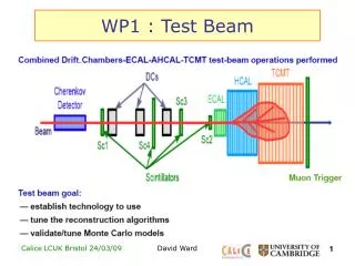
PM3 PM1 PM2 TIB1, TIB2, TIB3, TEC1, TEC2, TEC3, TOB1, TOB2, TOB3, TOB4, TOB5, TOB6 100, 50, 100, 100, 100, 100, 50, 50, 75, 100, 50, 100 () Experimental set-up • 2 boxes containing 3 TIB, 3 TEC and 6 TOB (non-irradiated) modules • APV25 was operated in peak mode throughout beam test • A range of RINV were used (50, 75, 100 ) Beam: 300 MeV pions (+/-) 72 MeV protons 20 ns bunch structure Detectors: TIB: pitch~120 m, thickness~300 m TEC: pitch~200 m (variable), thickness~500 m TOB: pitch~180 m, thickness~500 m Tommaso Boccali
X 10 Operating modes Normal trigger mode (for HIP rate measurement) 1 frame per trigger per APV identify HIP events through characteristic APV behaviour (saturated baseline, large signals) calculate the probability of a HIP event per trigger per plane per incident Multi trigger mode (for deadtime measurement) 3 frames per trigger per APV (triggers are spaced by 75 ns) the first trigger is followed by 9 forced trigger identify HIP events in the frame train follow the APV behaviour in time (10x3x25ns=750ns) Full picture of APV recovery Direct deadtime measurement on an event-by-event basis possible APV25 always operated in peak mode Tommaso Boccali
Physics program I~15 kHz, with pre-filter 300 MeV - beam I~300 kHz, with and without pre-filter I~1.2 MHz, with pre-filter I~25 kHz, with pre-filter, with and without APV25 operated in inverting mode 300 MeV + beam 72 MeV p beam Deadtime measurement: multi-trigger mode 300 MeV - beam pre-filter and backward veto pre-filter and backward veto 300 MeV + beam Tommaso Boccali
Beam profile Problems in the first TIB module Different pitches and geometric characteristics! Tommaso Boccali
Some examples of HIP events… Tommaso Boccali
CMMAX Identifying HIP events • CM sensitive to hardware settings • Positions of baseline and FED dynamic range define maximum CM shift CMMAX = peds – d0 • Define CMRATIO = CMABS / CMMAX allows comparison between APVs • Distributions grouped according to detector and resistor type • CM peak due to HIP events only • Pre-filter used before all triggers do not observe dead APV25s • c.f. X5: more pronounced peak, due to HIP events and dead APV25s • Select HIP events with CMRATIO -0.8 -and S>200 counts- Tommaso Boccali
HIP rate measurement Integral distribution of CM, normalised to number of good triggers, planes and incident pions (at 90 degrees !) Preliminary HIP rates: TIB 50 (2.3±0.1) 10-4 TIB 100 (3.7±0.1) 10-4 TEC (100) (6.2±0.1) 10-4 TOB ~50 (5.5±0.1) 10-4 TOB 75 (5.8±0.2) 10-4 TOB 100 (6.2±0.1) 10-4 clear factor between 300 m and 500 m confirmation of the reduction of HIP rate with smaller Rinv Linear behaviour with thickness HIP cut - runs - 1/2 stat. - Runs with + give similar results Tommaso Boccali
overshoot (>400 ns) recovery time (~250 ns) dead-time (<~100 ns) Deadtime measurement Profile histos of the average CM vs time grouped according to modules and resistors X5 (+lab) results confirmed with much higher accuracy chips with lower resistors recover first “reasonable” CM value restored after ~300 ns Work to do in order to find the “true” dead-time value Tommaso Boccali
325 ns 575 ns 450 ns 425 ns 475 ns 350 ns 500 ns 125 ns 0 ns 275 ns 525 ns 550 ns 300 ns 375 ns 150 ns 200 ns 100 ns 625 ns 75 ns 225 ns 600 ns 400 ns 250 ns 50 ns 175 ns 25 ns Example of APV25 recovery HIP happens ! (t=0 s) 400 ADC counts The chip is dead Recovery starts (t~100 ns) is the chip really alive again? The typical CM slope when recovering is clearly visible Nominal baseline Overshooting now (t~400 ns) Hit strips sort of “frozen” to original ADC values (peak mode!) microseconds to perfect recovery? Digital zero 100 ADC counts Tommaso Boccali
~4 ~5x10⁻⁴/500 m Interpretation The induced cluster reconstruction inefficiency induced by dead-time is, per unit traversed length (300 MeV ): weighted local occupancy pessimistic estimates for low luminosity: TIB, TOB ~1 (Tommaso) Inefficiency induced at low luminosity (worst case, assuming dead-time=4 BX) TIB ~ 1x10⁻³, TOB ~ 2x10⁻³ (factor 3/5) another factor 5 to be assumed for high luminosity 0.5-1% inefficiency regime Tommaso Boccali
DAQ problems: scan of some bad event ... Tommaso Boccali
CM distributions after event filtering TOB: Tommaso Boccali
How do we define the hip rate ? ped-d0 = 116 Depending on apv settings, common mode saturates at different values TOB1 ped-d0 = 58 • Two (?) effects: • saturation due to finite dynamic range • saturation of apv pre-ampl or apv inverter TOB2 ped-d0 = 122 TOB3 ped-d0 = 100 TOB4 vpsp pedestal negative dynamic-range ped-d0 = 121 TOB5 ped-d0 = 107 Tommaso Boccali TOB6
First test: select events with low rms Use the rms of truncated raw signal distribution: when the apv is saturated, the raw signal is forced to the digital 0 value, giving very low rms values. CM < -80. Tommaso Boccali
Alternative approach: relate the HIP rate to a physical cross section p ds P(E>Ecut) = P(CM<CMcut) dE p p • Assumption: for the same E all the CM baselines go down by the same amount. Then: • P(CM < CMcut) ~ P(E>Ecut) • all modules with the same thickness have the same rate • This assumption may be broken if: • different Rinv imply different CM shifts for same E • apv pre-ampls are not the same and saturate at different values • ? .... Tommaso Boccali
Rates as function of CM cuts Hip rates assuming one track per event (could scale up by 20-30% because of bad DAQ events) warning: hip events involving more than one module are multi-counted ! Tommaso Boccali
Preliminary results on dead/recovery time RUNS analysed: 0040290-0040295 HIP selected by RMS<1 Tommaso Boccali
Cluster width Tommaso Boccali
Conclusioni? • Nessuna in realta’, I numeri definitivi saranno dati alla tracker week • Comunque: • Hip rate dell’ ordine di 2-6 x 10⁻⁴ e scalano come atteso fra 300 um e 500 um. • Non e’ chiarissimo quanto I 50 Ohm su Rinv migliori le cose. In laboratorio il miglioramento era piu’ forte • Abbiamo anche dei dati non analizzati senza inverter. L’Hip rate dovrebbe essere esattamente zero; da studiare quanto sia fattibile… • Recovery time: ancora problemi di definizione, dovendo dare un numero direi 4-10 bunch crossings Tommaso Boccali
Conclusioni? • Impatto dei protoni, l’HIP rate dovuto a ionizzazione da parte di protoni da < 100 MeV dovrebbe essere alto (per fortuna abbiamo il campo magnetico!) • Recovery time: cosa possiamo fare nel recovery time, quando la baseline e’ storta? E’ possibile pensare/implementare nel FED qualcosa di piu’ furbo dell’ attuale. Calcolare il common mode su 32 invece che su 128 strip per esempio potrebbe gia’ aiutare parecchio…. Tommaso Boccali
Conclusioni? Dead time: Roberto da’ 2 x 10⁻³ con soli 4 bunch crossings per il recovery a bassa luminosita’ … non voglio commentare questo numero, vorrei solo dire che un fattore 5 di incertezza per vari motivi non puo’ essere escluso! Tommaso Boccali