Download
1 / 36
380 likes | 595 Views
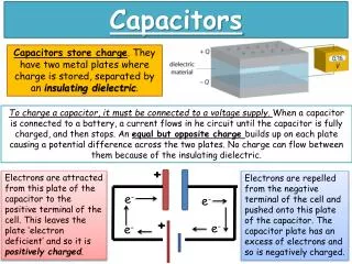
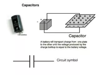
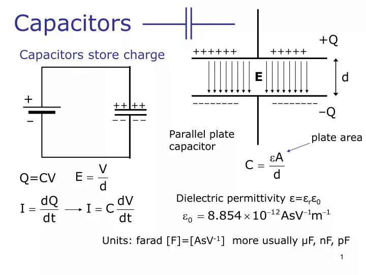
Capacitors. +Q. ++++++ +++++. Capacitors store charge. E. d. +. –––––––– –––––––– . ++ ++. –Q. –. – – – –. Parallel plate capacitor. plate area. Q=CV. Dielectric permittivity ε = ε r ε 0. Units: farad [F]=[AsV -1 ] more usually μ F, nF, pF. Capacitor types.

E N D
Capacitors +Q ++++++ +++++ Capacitors store charge E d + –––––––– –––––––– ++ ++ –Q – – – – – Parallel plate capacitor plate area Q=CV Dielectric permittivity ε=εrε0 Units: farad [F]=[AsV-1] more usually μF, nF, pF
Capacitor types Range Maximum voltage Ceramic 1pF–1μF 30kV Mica 1pF–10nF 500V (very stable) Plastic 100pF–10μF 1kV Electrolytic 0.1μF–0.1F 500V Parasitic ~pF Polarised
Capacitors C1 C2 C3 Capacitors in parallel: C1 C2 C3 Capacitors in series: Q1=Q2 +Q1 –Q1 +Q2 –Q2 V1 V2
Capacitors – energy stored Energy stored as electric field
RC circuits 1 Initially VR=0 VC=0 2 R Switch in Position “1” for a long time.Then instantly flips at time t = 0. Capacitor has a derivative! How do we analyze this? There are some tricks… + + 1 V0 I + C ALWAYS start by asking these three questions: 1.) What does the Circuit do up until the switch flips? (Switch has been at pos. 1 for a VERY long time. easy) 2). What does the circuit do a VERY long time AFTER the switch flips? (easy) 3). What can we say about the INSTANT after switch flips? (easy if you know trick)
The Trick!! • Remember • Suppose the voltage on a 1 farad Capacitor changes by 1 volt in 1 second. • What is the current? • What if the same change in V happens in 1 microsecond? • So…What if the same change in V happens instantly? • Rule: It is impossible to change the voltage on a capacitor instantly! • Another way to say it: The voltage at t = 0-e is the same as at t = 0+e. Note for Todd : Put problem on board and work through these points!
RC circuits 1 Initially at t = 0-VR=0 VC=0 I=0 2 R + 1 V0 I C Then at t = 0+Must be that VC=0 If VC=0 then KVL says VR=V0 and I=V0/R.Capacitor is acting like a short-circuit. 2 differentiate wrt t Finally at t = +∞VR=0 VC=V0 I=0
R + V0
Capacitor as integrator Integrator R Vi Vint C If RC>>t VC<<Vi
Differentiation C Vi Vdiff R Small RC
Inductors Electromagnetic induction Solenoid N turns B I Vind
Self Inductance I for solenoid Mutual Inductance M I Units: henrys [H] = [VsA-1]
Inductors Wire wound coils - air core - ferrite core Wire loops Straight wire
Series / parallel circuits L1 L2 L3 Inductors in series: LTotal=L1+L2+L3… I Inductors in parallel I2 I1 L1 L2
Inductors – energy stored Energy stored as magnetic field
The Next Trick!! • Remember • Suppose the current on a 1 henry Inductorchanges by 1 amp in 1 second. • What is the voltage? • What if the same change in I happens in 1 microsecond? • So…What if the same change in I happens instantly? • Rule: It is impossible to change the current on an inductor instantly! • Another way to say it: The current at t = 0-e is the same as at t = 0+e. • Does all this seem familiar? It is the concept of “duality”.
Initially t=0-VR=V0 VL=0 I=V0/R RL circuits 2 R + + + 1 V0 At t=0+ Current in L MUST be the sameI=V0/R So… VR=V0 VR20=20V0and VL = -21V0 !!! I L 20R + For times t > 0 And at t=∞ (Pos. “1”)VR=0 VL=0 I=0
R + V0 L Notice Difference in Scale!
I2 R2 + V0 L R1 t<0 switch closed I2=? t=0 switch opened t>0 I2(t)=? voltage across R1=? Write this problem down and DO attempt it at home
Notes for Todd: Try to do it cold and consult the backupslides if you run into trouble. Physics 3 June 2001
LCR circuit 2 R + 1 V0 L I(t)=0 for t<0 V(t) C
R, L, C circuits • What if we have more than just one of each? • What if we don’t have switches but have some other input instead? • Power from the wall socket comes as a sinusoid, wouldn’t it be good to solve such problems? • Yes! There is a much better way! • Stay Tuned!
2 RL circuits 1 Initially VR=0 VL=0 2 R + 1 V0 L
R + V0 L
R1 R0 L R0 L Norton R0 R0 V0 R1 R1 R1 L L
Energy stored per unit volume Inductor Capacitor