Download
1 / 52
540 likes | 680 Views
Single-spin detection and quantum state readout by magnetic resonance force microscopy. Goan, Hsi-Sheng 管 希 聖. Department of Physics National Taiwan University. Silicon-based quantum computing. Two interactions: hyperfine and exchange interactions.

E N D
Single-spin detection and quantum state readout by magnetic resonance force microscopy Goan,Hsi-Sheng 管 希 聖 Department of Physics National Taiwan University
Silicon-based quantum computing Two interactions: hyperfine and exchange interactions . Determining the strength of these two interactionsas function ofdonor depth, donor separation and surface gate configuration and voltage. • L.M. Kettle, H.-S. Goan, S.C. Smith, C.J. Wellard, L.C.L. Hollenberg and C.I. Pakes, “A numerical study of hydrogenic effective mass theory for an impurity P donor in Si in the presence of an electric field and interfaces'', Physical Review B 68, 075317 (2003). • C.J. Wellard, L.C.L. Hollenberg, F. Parisoli, L.M. Kettle, H.-S. Goan, J.A.L. McIntosh and D.N. Jamieson, “Electron exchange coupling for single donor solid-state spin qubits”, Physical Review B 68, 195209 (2003). • L.M. Kettle, H.-S. Goan, S.C. Smith, L.C.L. Hollenberg and C.J. Wellard, ”Effect of J-gate potential and interfaces on donor exchange coupling in the Kane quantum computer architecture'', Journal of Physics: Condensed Matter 16, 1011 (2004). • C.J. Wellard, L.C.L. Hollenberg, L.M. Kettle and H.-S. Goan, “Voltage control of exchange coupling in phosphorus doped silicon”,Journal of Physics: Condensed Matter 16, 5697 (2004). • L. M. Kettle, H.-S. Goan, and S. C. Smith, “Molecular orbital calculations of two-electron states for P donor solid-state spin qubits”,cond-mat/0512200.
Quantum gate operation, and quantum algorithm modelling CNOT • C. D. Hill and H.-S. Goan, “Fast non-adiabatic two-qubit gates for the Kane quantum computer”, Physical Review A 68, 012321 (2003). • C.D. Hill and H.-S. Goan, “Comment on Grover search with pairs of trapped ions“, Physical Review A 69, 056301 (2004). • C.D. Hill and H.-S. Goan, “Gates for the Kane quantum computer in the presence of dephasing”, Physical Review A 70, 022310 (2004). • C. D. Hill, L. C. L. Hollenberg, A. G. Fowler, C. J. Wellard, A. D. Greentree, and H.-S. Goan,“Global control and fast solid-state donor electron spin quantum computing”, Physical Review B 72, 045350 (2005). • C.D. Hill and H.-S. Goan, “Fast non-adiabatic gates and quantum algorithms on the Kane quantum computer in the presence of dephasing”,AIP Conference Proceedings Vol. 734, pp167-170 (2004).
Mesoscopic qubit and quantum measurement theory Coupled quantum dots measured by a point contact detector • H.-S. Goan,“Quantum measurement process of a coupled quantum dot system”,invited book chapter in “Trends in Quantum Dots Research”, Ed. By P.A. Ling (Nova Science, New York, 2005) pp.189-227 • H.-S. Goan, “An analysis of reading out the state of a charge quantum bit”,Quantum Information and Computation 3, 121-138 (2003). • H.-S. Goan and G. J. Milburn, “Dynamics of a mesoscopic charge quantum bit under continuous quantum measurement”,Physical Review B 64, 235307 (2001). • H.-S. Goan, G. J. Milburn, H. M. Wiseman, and H. B. Sun, “Continuous quantum measurement of two coupled quantum dots using a point contact: A quantum trajectory approach”,Physical Review B 63, 125326 (2001).
Monte Carlo method for a quantum measurement process • H.-S. Goan, “Monte Carlo method for a quantum measurement process by a single-electron transistor”,Physical Review B 70, 075305 (2004). • T.M. Stace, S.D. Barrett, H.-S. Goan and G.J. Milburn, “Parity measurement of one- and two-electron double well system”,Physical Review B 70, 205342(2004). • H.-S.Goan, “Monte Carlo method for a superconducting cooper-pair-box charge qubit measured by a single-electron transistor”, in “Quantum Computation: solid state systems” ed. by P. Delsing, C. Granata, Y. Pashkin, B. Ruggiero and P. Silvestrini, (Springer, New York, 2005) pp.171-179. Superconducting Cooper-pair box qubit measured by a single electron transistor
Quantum electromechanical systems • Single Fullerene (C60) molecular transistor • Shuttle systems (Park et al., 2000) (Shekhter et al., 2003) • D.W. Utami, H.-S. Goan, and G.J. Milburn, “Transport properties of a quantum electromechanical system”,Physical Review B 70, 075303 (2004). • D.W. Utami, H.-S. Goan, C.A. Holmes and G.J. Milburn, “Quantum noise in the electromechanical shuttle”,cond-mat/0509748. • J. Twamley, D.W. Utami, H.-S. Goan, and G. J. Milburn, “Spin detection in a quantum electromechanical system”,cond-mat/0601448.
Quantum jump transitions in mesoscopic mechanical systems Investigate the possibility of experimental observation ofquantized energy state (discrete Fock state) transitions (i.e., quantum jumps) in a nano-mechanical oscillator. (Curtsey of Roukes's group at Caltech) • D.H. Santamore, H.-S. Goan, and G.J. Milburn and M.L. Roukes, “ Phonon number measurement of a quantum electromechanical system”, Physical Review A 70, 052105(2004).
Resonator and cold ion system W.K. Hensinger, D.W. Utami, H.-S. Goan, K. Schwab, C. Monroe, and G.J. Milburn, “Ion trap transducers for quantum electromechanical oscillators”, Physical Review A (Rapid Communications) 72, 041405(2005).
Quantum feedback control in circuit QED • M. Sarovar, H.-S. Goan, T. P. Spiller, and G. J. Milburn, “High fidelity measurement and quantum feedback control in circuit QED” , Physical Review A 72, 062327(2005). Nature 431, 162 (2004); A. Blais et al., Physical Review A 69, 062320 (2004)
Single spin detection by magnetic resonance force microscopy D. Rugar et al., Nature430, 329 (2004): • T.A. Brun and H.-S. Goan, “Realistic simulations of single-spin nondemolition measurement by magnetic resonance force microscopy”, Physical Review A 68, 032301 (2003). • G.P. Berman, F. Borgonovi, H.-S. Goan, S.A. Gurvitz, and V.I. Tsifrinovich, “Single-spin measurement and decoherence in magnetic resonance force microscopy”, Physical Review B 67, 094425 (2003). • H.-S. Goan, and T.A. Brun, “Single spin measurement by magnetic resonance force microscopy: Effect of measurement device, thermal noise and spin relaxation”, Proceedings of SPIE, 5276, 250-261 (2004). • T. A. Brun and H.-S. Goan,“Realistic simulations of single-spin measurement via magnetic resonance force microscopy”,International Journal of Quantum Information 3, 1-9 Suppl. (2005).
Research • Solid-state quantum computing (impurity donors in semiconductors; superconductor Josephson junctions; quantum dots) • Theoretical mesoscopic physics • Theoretical condensed matter physics • Nano (Quantum) electro-mechanical systems • Quantum measurement theory and quantum feedback control • Single-spin and single-charge detection • Spintronics • … People • 3 Ph.D. students and 2 Master students • Getting 1 postdoctoral fellow Collaborators • Prof. Gerard J. Milburn(U. of Queensland, Australia) • Prof. Todd A. Brun(U. of Southern California, USA) • Prof. Jason Twamley (U. of Macquarie, Australia) • Former UQ Ph.D. students: Louise Kettle, Charles Hill, Dian Utami
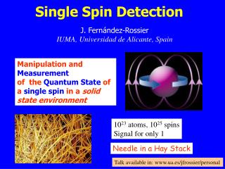
Single-spin detection • Single-spin measurement is an extremely important challenge, and necessary for the future successful development of several recent spin-based proposals for quantum information processing. • There are both direct and indirectsingle-spin measurement proposals: • Direct proposals: SQUID, MRFM • Indirect proposal: Spin-dependent charge transport, spin-dependent optical transition. • The idea behind some indirect proposals is to transform the problem of detecting a single spin into the task of measuring charge transport since the ability to detect a single charge is now available. • Magnetic resonance force microscopy (MRFM) has been suggested as a promising technique for single-spin detection [Sidles (’92), Berman et.al.(’02)]. • To date, MRFM technique has demonstrated with single-spin sensitivity ! D. Rugar’s group (’04)
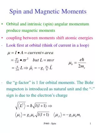
Readout concept Step 1: Convert spin to charge Step 2: Measure charge • Spin magnetic moment: mB =9.310-24JT-1is very small! • Use spin to charge conversion with fast charge read-out • Apply magnetic field to split the spin up and down by the Zeeman energy with appropriate dot potential.
B=0 B>0 DEZ charge SPIN UP 0 -e time N = 1 charge SPIN DOWN 0 -e time ~G-1 N = 1 N = 0 N = 1 Spin-to-charge conversion Use Zeeman splitting DEZ=gmBB
T B// DRAIN Q IQPC G M R P 200 nm SOURCE Single spin readout spin to charge conversion + fast charge detection + EZ = gmBB ….single spin measurement ? =
Single spin detection by magnetic resonance force microscopy D. Rugar et al., Nature430, 329 (2004): • T.A. Brun and H.-S. Goan, “Realistic simulations of single-spin nondemolition measurement by magnetic resonance force microscopy”, Physical Review A 68, 032301 (2003). • G.P. Berman, F. Borgonovi, H.-S. Goan, S.A. Gurvitz, and V.I. Tsifrinovich, “Single-spin measurement and decoherence in magnetic resonance force microscopy”, Physical Review B 67, 094425 (2003). • H.-S. Goan, and T.A. Brun, “Single spin measurement by magnetic resonance force microscopy: Effect of measurement device, thermal noise and spin relaxation”, Proceedings of SPIE, 5276, 250-261 (2004). • T. A. Brun and H.-S. Goan,“Realistic simulations of single-spin measurement via magnetic resonance force microscopy”,International Journal of Quantum Information 3, 1-9 Suppl. (2005).
Magnetic resonance imaging • Magnetic Resonance Imaging (MRI) principle: if the precessing frequency of magnetic moments in a uniform magnetic field is driven on resonance by an external ac magnetic field, the resulting signal reveals something about the spin state of the magnetic moments and the external magnetic environment in which they are placed. • At least approximate amount of 1012 nuclear spins or 107 electron spins is required to generate a measurable MRI signal (via conventional inductive detection techniques). • Compared to MRI, MRFM technique provides considerable improvements in sensitivity (minimum force detectable) and spatial resolution.
Laboratory frame and rotating reference frame Laboratory frame Reference frame
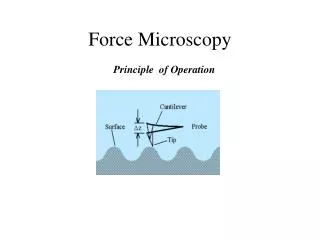
MRFM setup • A uniform magnetic field in the z-direction. • A ferromagnetic particle (small magnetic material) mounted on the cantilever tip producing a magnetic field gradient on the single spin. • As a result, a reactive force (interaction) acts back on the magnetic cantilever tip in the z-direction from the single spin.
Schematic illustration of MRFM (John Sidles’s group at UW, Seattle, USA)
MRFM animation http://www.almaden.ibm.com/vis/models/ models.html#mrfm
What is the use of MRFM? MRFM combines four different technologies to serve as a sensing and imaging device: • 3-dimensional non-destructivemagnetic resonance imaging, • atomic-level resolutionatomic force microscopy, • mobile scanning probe microscopyallowing in-situ and direct observation, • continuous observationor readout technique. • the direct observation of individual molecules (or other nanoscale devices or materials), • in situ, in their native forms and native environments, • with three-dimensional atomic-scale resolution, • by a nondestructive observation process.
Single-spin detection by MRFM • But the required averaging time is still too long to achieve the real-time readout of the single electron spin quantum state. • The ability to accomplish the single spin magnetic resonance detection at a spatially resolved location would fulfil an important requirement for many quantum computation schemes. • Moreover, the ability to detect a single nuclear spin would have tremendous impacts on the fields of quantum information processing, quantum computation, data storage, nanometre-scale electronics, materials sciences, biology, biomedicine, and etc. D. Rugar et al., Nature430, 329 (2004): demonstrated to achieve a detection sensitivity of a single electron spin.
MRFM CAItechnique • The interaction between the single spin and the cantilever is rather weak. • In the MRFM cyclic adiabatic inversion (CAI) , the cantilever is driven at its resonance frequency to amplify the otherwise very small vibrational amplitude. • This is achieved by a modulation scheme using the frequency modulation of a rotating radio-frequency (RF) magnetic field in the x-y plane. The frequency modulationis aperiodic functionin time with the resonant frequency of the cantilever.
Spin-cantilever Hamiltonian In the reference frame rotating with the RF field,
Principle of single-spin measurement I. • In the case when the adiabatic approximation is exact, the instantaneous eigenstates of the spin Hamiltonian in the rotating reference frame of the RF field are the spin states parallel or antiparallel to the direction of the effective magnetic field • If denoted as respectively. • We define an operatorfor the componentof spin along this axis.
Principle of single-spin measurement II. • Starting at a general initial spin state in the basis • In the basis of the instantaneous eigenstates of where initial angle between and z-axis direction
Principle of single-spin measurement III. • Following from the adiabatic theorem: where are instantaneous eigenvalues. • Probabilities and remainthe same at all times. • This provides us with an opportunity to measure the initial spin state probabilitiesat later times.
How do we measure these spin state probabilities? • The idea is to transfer the information of the spin state to the state of the driven cantilever. • In the interaction picture in which the state is rotating with the instantaneous eigenstates of the spin Hamiltonian, the spin-cantilever interaction can be written as: • The phase of the driven cantilever vibrations depends on the orientation of the spin states. • Numerical simulations (with reasonable parameters for the CAI approximations) indicate that as the amplitude of the cantilever vibrations increases with time, the phase difference in the oscillations for thetwo different initial spin eigenstates ofapproaches
Parameters • We chose our parameters based on those used by G.Berman et. al. , J. Phys. A: Math. Gen. 36, 4417 (2003). • These values are • (in arbitrary units): • The frequency modulation (driving force):
Measurement scheme and device • The cleaved end of the fiber and the vibrating cantilever form a cavity. As the cantilever moves, the resonant frequency of the cavity changes. • Because the time scale of the cantilever's motion is very long compared to the optical time scale, we can treat the effects of this in the adiabatic limit. • The cavity mode is also subject to driving by an external laser, and has a very high loss rate. • In the bad cavity limit, the dynamics of field quadrature (x) adiabatically follows that of cantilever position. • Phase-sensitive homodyne measurementon the field quadrature of the cavity mode bya fiber-optic interferometer: phases of the cantilever vibrations. state of the single spin.
MRFM setup • A uniform magnetic field in the z-direction. • A ferromagnetic particle (small magnetic material) mounted on the cantilever tip producing a magnetic field gradient on the single spin. • As a result, a reactive force (interaction) acts back on the magnetic cantilever tip in the z-direction from the single spin.
Stochastic master equation approach • Consider various relevant sources of noise: • cantilever in a thermal bath and interacting with the cavity mode • cavity modesubject to driving by an external laser and interacting with continuum of electromagnetic modes outside the cavity • Develop a continuous measurement model:a stochastic master equation represents the evolution conditioned on the photocurrent measurement record. • For numerical purpose, it is often easier to unravel the master equation to a stochastic Schrodinger equation. • Additional stochastic process represents afictitious additional measurement, whose outcome we average over to recover the state which is conditioned ontheactual measurement. • Present some simulation results for the single-spin measurement process.
Trajectories for the superposition state The spins quickly localize onto either up or down state, but the cantilever takes longertime to register this visibly.
Output Noise Spectrum • The term independent of frequency is the contribution from the shot noise of the photons. • The blue curve is the ``back-action'' noise on the position of the cantilever by the radiation, due to the random way in which photons bounce off the cantilever. • The red curve is the thermal noise, due to the thermal Brownian-motion fluctuation of the cantilever.
High-frequency vibrational noise • High frequency vibrational noise of the cantilever tip may cause fast spin relaxation[Mozyrsky et al. (03)] Laboratory frame Reference frame
Mass-loaded cantilever Chui et al. (03) • Mass-loaded design to reduce the high frequency vibrational noise • Superconducting RF resonator • Cantilever perpendicular to the sample • InterruptedOScillating Cantilever-driven Adiabatic Reversal(iOSCAR)protocol. SmCo
Near the surface, the cantilever frequency is affected not only by the presence of the spins but also by the more dominant electrostatic and van der Waals forces. To make the spin signal distinctive: periodically reverse the sign of the frequency shift by interrupting the microwave power for 1/2 cycle of the cantilever vibration every Nint cycles. the spin signal fsig = fc/2Nint. Use a lock-in amplifier referenced to fsig to demodulate the frequency shift and determine Df Interrupted OSCAR protocol OScillating Cantilever-driven Adiabatic Reversal(OSCAR) protocol.
Single-spin detection by MRFM • But the required averaging time is still too long to achieve the real-time readout of the single electron spin quantum state. • The ability to accomplish the single spin magnetic resonance detection at a spatially resolved location would fulfil an important requirement for many quantum computation schemes. • Moreover, the ability to detect a single nuclear spin would have tremendous impacts on the fields of quantum information processing, quantum computation, data storage, nanometre-scale electronics, materials sciences, biology, biomedicine, and etc. D. Rugar et al., Nature430, 329 (2004): demonstrated to achieve a detection sensitivity of a single electron spin.
Recent experiments on MRFM Improvements in detection signal-to-noise ratio should allow real-time quantum state detection and feedback control of individual electron spins
Conclusion • Simulation resultsindicate thatthe single-spin readout by MRFM is possible. • The parameters we assumed for the simulations were somewhat optimistic (field gradient: 107 T/m vs. 105 T/m; T: 0.1K vs. 0.2K); Steady improvement in these techniques, however, should make single-spin measurement more efficient and effective. • To be a good quantum measurement, the effects which can flip the spin must remain small. Future work • Take into account • effect of higher-order cantilever vibrational modes • domain motion, thermal magnetic noise in the tip • other modulation schemes, multiple spins • quantum feedback control
Animation of single spin detection using interrupted OScillating Cantilever-driven Adiabatic Reversalprotocol