Download

1 / 125
1.67k likes | 2.78k Views
BOEING 737-200. La llave que se usa constantemente reluce como plata: no usándola se llena de herrumbre. Lo mismo pasa con el entendimiento “ Benjamin Franklin” si sabes lo que tienes que hacer y no lo haces, entonces estas peor que antes “Confucio” ¡Estudia vagabundo!

E N D
BOEING 737-200 La llave que se usa constantemente reluce como plata: no usándola se llena de herrumbre. Lo mismo pasa con el entendimiento “Benjamin Franklin” si sabes lo que tienes que hacer y no lo haces, entonces estas peor que antes “Confucio” ¡Estudia vagabundo! “Pedro Rodriguez” Ing. Pedro Rodriguez
ENGINE INDICATING - DESCRIPTION engine pressure ratio (EPR) indicating system a tachometersystem (N1 Y N2) exhaust gas temperature (EGT) indicatingsystem airbornevibrationmonitoringsystem
BOEING 737-200 • ¿whatisitgoodfor? Ing. Pedro Rodriguez
BOEING 737-200 Ing. Pedro Rodriguez
BOEING 737-200ENGINE PRESSURE RATIO INDICATING SYSTEM Ing. Pedro Rodriguez
BOEING 737-200 oneinletpressure(Pt2) sensing probe six-exhaust pressure (Pt7) sensing probes Engine pressure ratio transmitter pressure ratio indicator for each engine. • used for setting engine thrust • for monitoring engine performance Ing. Pedro Rodriguez
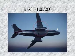
PT2 PT7 On this engine we determine the amount of thrust by measuring the Exhaust Pressure Ratio (EPR) - which is simply the Output air pressure divided by the Inlet air pressure. The math formula for EPR is : OUTLET/INLET= EPR The pt2 probe measures the inlet air pressure, while the pt7 probe measures the outlet air pressure. The current EPR for each engine is displayed on an EPR gauge. An indicator in the cockpit (called a Thrust Rating Indicator) displays an EPR value that is computed as maximum power for the engine. The pilot and the Autothrottles will not exceed this maximum computed EPR display during normal operations. Since a large amount of the thrust on this engine is delivered by the FAN; you can also determine the amount of thrust available by reading the N1 rotor RPM. Ing. Pedro Rodriguez
BOEING 737-200 • InletPressureSensingProbe: probe similar to a pitottube. This probe is mounted through the center of the nose dome with the open end of the tube facing the inlet air stream. The vent hole in the probe functions as the probe ice detector by decreasing engine inlet pressure (increasing EPR) when icing occurs. The probe is anti-iced by theengine anti-ice system. Ing. Pedro Rodriguez
BOEING 737-200 Ing. Pedro Rodriguez
BOEING 737-200 • A. Each engine has six exhaust (discharge, Pt7) pressure-sensing probes projected into the stream of turbine exhaust gases. The probes are connected to a common manifold for obtaining an average pressure of the exhaust gases. Exterior connection to the manifold is made at a single point through the fan discharge outer duct at approximately the seven o'clock position ExhaustPressureSensingProbe Ing. Pedro Rodriguez
BOEING 737-200 EnginePressure Ratio Transmitter located at STA 570 on the right and left side of the airplane in the air conditioning bay. ¿HOW TO LOCATE IT? • converts the exhaust pressure (Pt7) and the inlet pressure (Pt2) into a ratio, and generates three-phase electrical signals corresponding to pressure changes in the engine Ing. Pedro Rodriguez
BOEING 737-200 ¿A QUESTION TO MAKE? Ing. Pedro Rodriguez
BOEING 737-200 Ing. Pedro Rodriguez
BOEING 737-200 Ing. Pedro Rodriguez
BOEING 737-200 Ing. Pedro Rodriguez
BOEING 737-200TEST-questions-performe • Testing the engine pressure ratio (EPR) indicating system consists of two phases. The transmitter inlet (Pt2) and exhaust (Pt7) pressure lines are tested for leakage, and an operational test on the entire system is performed. The components included in this systems test are the pressure ratio transmitter, indicator, and the inlet and exhaust pressure lines. Ing. Pedro Rodriguez
BOEING 737-200 Equipment and Materials (1) An air pressure source with two individually regulated outlets, the pressure of which can be accurately set at pressures between 25.00 and 100.00 inches of mercury absolute. All pressures are to be monitored by pressure gages with an accuracy of |0.5%. Shutoff valves must be provided on the source side of all gages (Fig. 501). (2) Gage - Pressure, Model C, 0 - 50 or 0 - 100 inch HgA, 0.1% Full Scale, Hiese (3) ShutoffValve (4), A311 - 1/8" ID, DwyerInstr. (4) T-Fitting (4), A343-1 - 1/8" ID, Dwyer Instr. (5) Fitting (2), A339 - 1/8" ID, Dwyer Instr. (6) Tubing 30 feet, A225 - 1/8" ID, Dwyer Instr. (7) Wheatstone Bridge, Shallcross 638-R, Shalltronix Ing. Pedro Rodriguez
BOEING 737-200 Ing. Pedro Rodriguez
BOEING 737-200 Ing. Pedro Rodriguez
BOEING 737-200 Ing. Pedro Rodriguez
BOEING 737-200 Ing. Pedro Rodriguez
ENGINE INSTRUMENTS RAT oC 13 PLUS EPR LIM 2.02 TEST T.O. TO FLEX GA MCT CL CR NO MODE The Thrust Rating Indicator (TRI) is shown in green. This device will compute the maximum thrust that the pilot should operate for any given segment of the flight.
RAT oC 13 PLUS EPR LIM 2.02 TEST T.O. TO FLEX GA MCT CL CR NO MODE The Thrust Rating Indicator (TRI) receives temperature information from the RAT Probe. The pilot may select one of six modes on the TRI. The three buttons on the top row are for low altitude operations. The three buttons on the bottom row are for high altitude operations.
RAT oC DFGC #1 13 PLUS EPR LIM 2.02 TEST DFGC #2 T.O. TO FLEX GA MCT CL CR VOR LOC VERT SPD ALT HLD SPD SEL 250 181 V 0000 =2000 ILS IAS MACH MACH SEL AP ON AUTO LAND PERF TURB EPR LIM 1 2 The pilot can select which Digital Flight Guidance Computer (DFGC) is providing data to the TRI. The switch used to select either DFGC is located below the AP Engage Switch on the glareshield. NEXT to switch > NO MODE
RAT oC DFGC #1 13 PLUS EPR LIM 2.02 TEST DFGC #2 T.O. TO FLEX GA MCT CL CR NO MODE VOR LOC VERT SPD ALT HLD SPD SEL 250 181 V 0000 =2000 ILS IAS MACH MACH SEL AP ON AUTO LAND PERF TURB EPR LIM 1 2
RAT oC DFGC #1 13 PLUS EPR LIM 2.02 TEST DFGC #2 T.O. TO FLEX GA MCT CL CR NO MODE The pilot has moved the 1 - 2 Selector to the right. The #2 DFGC is now controlling the TRI. NEXT > VOR LOC VERT SPD ALT HLD SPD SEL 250 181 V 0000 =2000 ILS IAS MACH MACH SEL AP ON AUTO LAND PERF TURB EPR LIM 1 2
RAT oC 13 PLUS EPR LIM 2.02 TEST T.O. TO FLEX GA MCT CL CR NO MODE The TRI displays the maximum EPR that the Auto-throttle system will command. The TRI computes EPR limits based upon systems operations. For example, it reduces the displayed EPR Limit by about .02 EPR if the Air Conditioning is ON. The TRI also computes EPR limits based on Ice Protection system operation, and atmospheric conditions.
RAT oC 13 PLUS EPR LIM 2.02 TEST T.O. TO FLEX GA MCT CL CR NO MODE This TRI sets the upper limit for the Autothrottle System (ATS). The ATS is used from takeoff until landing on the MD-80. The TRI will reduce the EPR limit if the Engine and/or Airfoil Ice protection systems are operating - when in flight. However, it will not reduce the T.O. ; T.O. Flex ; or GA thrust limits for engine ice protection use since the MD-80 is not performance penalized for Engine Ice Protection Bleed air extractions during Takeoff or Go-around.
RAT oC 13 PLUS EPR LIM 2.02 TEST T.O. TO FLEX GA MCT CL CR NO MODE This TRI sets the upper limit for the Autothrottle System (ATS). The ATS is used from takeoff until landing on the MD-80. Here you see the Takeoff mode highlighted. The Takeoff EPR limit is computed and updated until the aircraft reaches 50 knots on takeoff. At 60 knots the Autothrottle System will “CLAMP”. “CLAMP” is the term used on the MD-80 when the autothrottle servo is not powered.
RAT oC 13 PLUS EPR LIM 2.02 TEST T.O. TO FLEX GA MCT CL CR NO MODE This TRI sets the upper limit for the Autothrottle System (ATS). The ATS is used from takeoff until landing on the MD-80. With the ATS servo clamped from moving the throttles - you will be able to manually move the throttles without restriction. When the throttles are Clamped - you may retard the throttles & reject the takeoff without fighting against the Autothrottle servo.
RAT oC 1.6 1.6 1.8 1.8 1.4 1.4 13 PLUS 1.2 1.2 2.0 2.0 EPR LIM 1.0 1.0 2.2 2.2 EPR EPR 2.00 0.8 0.8 2.4 2.4 1.00 1.00 TEST T.O. TO FLEX GA MCT CL CR NO MODE EPR CHEVRON BUGS - AUTOMATIC The EPR LIMIT is displayed on the TRI and also by automatic orange chevrons on the EPR gauges. When the ATS sets the throttles to the TRI displayed EPR value - the white EPR needle should point to the amber chevron. TRI power is used normally during takeoff and climb. Obviously while in cruise or descent - the ATS will retard the throttles and the white EPR needle will be pointing to less EPR than the EPR CHEVRON. NEXT to select various TRI modes >
RAT oC 13 PLUS EPR LIM 1.90 TEST T.O. TO FLEX GA MCT CL CR NO MODE EPR CHEVRON BUGS - AUTOMATIC 1.6 1.6 1.4 1.8 1.4 1.8 1.2 1.2 2.0 2.0 1.0 1.0 2.2 2.2 EPR EPR 0.8 0.8 2.4 2.4 1.00 1.00
RAT oC 13 PLUS EPR LIM 1.78 TEST T.O. TO FLEX GA MCT CL CR NO MODE EPR CHEVRON BUGS - AUTOMATIC 1.6 1.6 1.8 1.8 1.4 1.4 1.2 1.2 2.0 2.0 1.0 1.0 2.2 2.2 EPR EPR 0.8 0.8 2.4 2.4 1.00 1.00
RAT oC 13 PLUS EPR LIM 1.98 TEST T.O. TO FLEX GA MCT CL CR NO MODE EPR CHEVRON BUGS - AUTOMATIC 1.6 1.6 1.8 1.8 1.4 1.4 1.2 1.2 2.0 2.0 1.0 1.0 2.2 2.2 EPR EPR 0.8 0.8 2.4 2.4 1.00 1.00
RAT oC 13 PLUS EPR LIM 2.00 TEST T.O. TO FLEX GA MCT CL CR NO MODE EPR CHEVRON BUGS - MANUAL 1.6 1.6 1.8 1.8 1.4 1.4 1.2 1.2 2.0 2.0 If the TRI is inoperative - the maximum EPR allowed for any mode may be found in charts in the Flight Manual. The EPR limits that you find in the charts must be manually set on the EPR CHEVRON BUGS. To do this - you must first pull out on the set knobs on each EPR gauge. NEXT to animate > 1.0 1.0 2.2 2.2 EPR EPR 0.8 0.8 2.4 2.4 1.00 1.00
EPR CHEVRON BUGS - MANUAL 1.6 1.6 1.8 1.8 1.4 1.4 1.2 1.2 2.0 2.0 1.0 1.0 2.2 2.2 EPR EPR 0.8 0.8 2.4 2.4 1.00 1.00
EPR CHEVRON BUGS - MANUAL 1.6 1.6 1.8 1.8 1.4 1.4 1.2 1.2 2.0 2.0 2.00 1.0 1.0 2.2 2.2 EPR EPR 0.8 0.8 2.4 2.4 1.00 1.00
EPR CHEVRON BUGS - MANUAL 1.6 1.6 1.8 1.8 1.4 1.4 1.2 1.2 2.0 2.0 2.00 1.0 1.0 2.2 2.2 EPR EPR 0.8 0.8 2.4 2.4 1.00 1.00
EPR CHEVRON BUGS - MANUAL 1.6 1.6 1.8 1.8 1.4 1.4 1.2 1.2 2.0 2.0 2.00 2.00 1.0 1.0 2.2 2.2 EPR EPR 0.8 0.8 2.4 2.4 1.00 1.00
EPR CHEVRON BUGS - MANUAL 1.6 1.6 1.8 1.8 1.4 1.4 1.2 1.2 2.0 2.0 Notice that when the knob is pulled out - a white readout appears to show the current position of the EPR CHEVRON BUG. With the knob pulled out - you may move the chevronby dialing the knob; the white readout will also change when you dial the knob. The white readout helps select the exact EPR limit - since the chevrons are difficult to set precisely due to their size. Normally the knobs are pushed in - and the upper readout is covered. In the automatic mode, the chevrons are positioned by the TRI. NEXT > 2.00 2.00 1.0 1.0 2.2 2.2 EPR EPR 0.8 0.8 2.4 2.4 1.00 1.00 To Replay - 28 ENTER
JT8D-217 JT8D-217A JT8D-219 RAT oC RAT oC RAT oC 12 12 12 PLUS PLUS PLUS EPR LIM EPR LIM EPR LIM 1.94 2.04 2.08 160 160 160 TEST TEST TEST 320 320 320 T.O. TO FLEX GA T.O. TO FLEX GA T.O. TO FLEX GA MCT CL CR MCT CL CR MCT CL CR NO MODE NO MODE NO MODE TRI TEST NEXT to animate a TRI test >
JT8D-217A RAT oC 04 MINUS EPR LIM 2.00 TEST T.O. TO FLEX GA MCT CL CR NO MODE After the test, the TRI displays NO-MODE. A mode must be selected for takeoff - or the Autothrottle system will not engage properly during the takeoff.
RAT oC 13 PLUS EPR LIM 2.00 TEST T.O. TO FLEX GA MCT CL CR NO MODE TRI NO-MODE The TRI can NO-MODE for various reasons. One reason is that there is no mode selected after the TRI test is conducted. Other reasons are: - No Air Cond. supplies are on when selecting MCT, CL, or CR - all considered high altitude modes. - Airfoil Anti-ice ON but Engine Anti-ice is not ON. - Airfoil Anti-ice ON but both pneumatic crossfeeds closed. - During single engine operation - both pneumatic crossfeeds open. - Use of engine or airfoil ice protection when the outside temperature is too warm. In review: the TRI will NO-MODE if you don’t have the bleed situation properly set. NEXT >
AUTOMATIC RESERVE THRUST (ART)
AUTOMATIC RESERVE THRUST FF FUEL CTL FUEL / OIL COOLER T R FUEL FILTER PRESS DROP The ARTS solenoid is added to the Fuel Control Unit to automatically increase the fuel flow to the engine to provide higher thrust during takeoff when: • Normal takeoff thrust is used • An engine fails or electrical power is interrupted • the aircraft is taking off from the ground with the ART system armed. The ART solenoid normally reduces the fuel flow slightly for takeoff - but when activated, it will allow full fuel to flow. MAXIMUM thrust is achieved electronically without advancing the throttles. When the ART solenoid activates - the “TRI” EPR limit display will increase. Both the ART and the TRI are controlled by the selected Digital Flight Guidance Computer. R INLET FUEL PRESS LOW