Download
1 / 26
260 likes | 367 Views
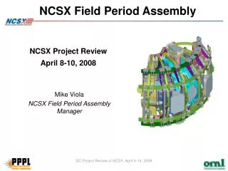
NCSX Field Period Assembly. October 31, 2007 Mike Viola Field Period Assembly Manager. +. +. =. FPA is Accomplished in Four Stages. Station 1 - VV Prep. Station 2 - MC Half Period Assembly. Station 3 - MCHP installation over VV Period. Station 5 - Final Assembly in NCSX Test Cell.

E N D
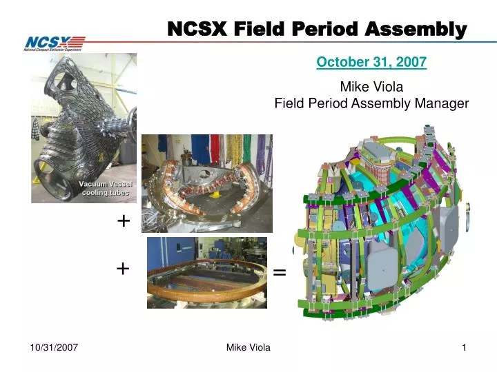
NCSX Field Period Assembly October 31, 2007 Mike Viola Field Period Assembly Manager + + = Mike Viola
FPA is Accomplished in Four Stages Station 1 - VV Prep Station2 - MC Half Period Assembly Station3 - MCHP installation over VV Period Station5 - Final Assembly in NCSX Test Cell Station6 – Final Machine Assembly – Erik Perry Mike Viola
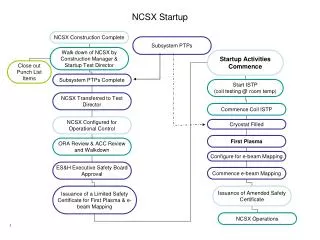
FPA Manufacturing, Inspection, Test, Quality Assurance Plan (MIT/QA) Complete Input (Station specific): Dimensional Control Plan (Art Brooks) FPA Assembly Sequence Plan (Tom Brown) FPA Specification and Assembly Drawings (Mike Cole) MIT/QA Plan provides basis for individual procedures to perform tasks then revised to include developed improvements. FPA Procedures FPA station 1 procedure complete and active FPA station 2 trials are providing input to procedure development DAILY ACTIVITY REVIEW MEETING Report day’s progress provide clear guidance for next day Obtain instant feedback from ORNL design team FPA Process Definitions Mike Viola
Documentation and Integrated Safety Management (ISM) Work Plans Manufacturing Facility Operation Plan (MFOP) completed for overall facility conduct using ISM as its basis. Job Hazards Analysis (JHA) developed for FPA activity Main hazard: components must be lifted by crane – many lifts will occur in several orientations. Lift procedures with individual lift data sheets are developed for each type of lift Activities Certification Committee (ACC) independently reviews each station setup, operations, and plans before station is activated. Station 1 review complete and declared operational Station 2 trials review complete “SAFELY SAFELY SAFELY” Mike Viola
We have a schedule, system, and people that enable us to detect our problems in advance and develop resolutions and implement them in a timely manner. Measure all modular coils in advance of assembly developed new alignment techniques Complete designs earlier to minimize configuration changes not rely on concurrent engineering as much during assembly phase Augmented metrology team and back office support two additional engineers each. Augmented trials to discover problems BEFORE the critical path. Added stud tension, bushing, nose weld trials Problem resolution and Management Improvements Metrology (Nothing can be checked with a ruler) Concurrent Engineering Problems discovered in field without time to resolve History of growth due to complexity Tolerance budget is divided throughout the fabrication Design uncertainty and lack of timely drawings Mike Viola
VV #1 and VV #2 98% Complete VV #3 90% Complete Cooling tube testing and final scans remain NCSX Vacuum Vessel Station 1 95% Complete VV #1 VVSA with ports welded VV #3 completing diagnostic loops VV #2 Mike Viola
Station 1 is 98% complete. Station 2 concepts have been developed and tested. Wedges are in use for pre-measurements. Metrology teams are stable and achieving repeatable results. Extensive analysis and testing has arrived at an acceptable joint design. Station 3 MC manipulation has been successfully simulated. Station 5 is at preliminary design level and time is included in the schedule for trials. Step by step review of Assembly Sequence and Potential Issues Mike Viola
Station 2 FPA trials enhanced and well in progress: Gross fit individual mating coils found minor interferences that are all understood and straightforwardly resolved in a few days. Joint design trials for Station 2 (useful for Station 3 also): Install and torque bolts – assess accessibility COMPLETE Incorporated into coil punchlist activity Develop shim technique COMPLETE Incorporated into shim design Pillow shims TRIALS COMPLETE New welded design for nose TRIALS COMPLETE Install Alumina coated metal shims Shims on order Install shims and bolt bushings in vertical orientation Preliminary design level for Station 3 and 5 Station 2 Mike Viola
Station 2 Assembly Sequence Potential Issues andMitigation Plans • Tooling not rigid enough – RETIRED • wedges determined to be adequate • Coils still to flexible –RETIRED • physically racked (twisted) coils to re-establish coordinate system • Alignment not within tolerances bars- RETIRED • iterated until met requirements • Shim thicknesses do not match inventory • fabricate/order new shims Assembly Steps/Major Activities • MC Fit-up Check Verify MC’s of MCHP will come together (Gross Fit-up) • Pre-Measurement of MHCP Type A/B/C Coil Flanges & Interfacing Type A Coil Flange Verify that the individual coils can be racked into proper shape. Verify that metrology measurements can be accurately taken and reproduced. • Alumina Shim Sizing & Preparation • Define shim sizes and compress to arrive at satisfactory shim set for MCHP assembly. • Pre-Installation Station 2 Set-up (for First Article Only) • Tooling/fixtures setup. • Pre-Assembly A-A - DELETED – ACCOMPLISHED IN STEP 2 above. Mike Viola
Station 2 Assembly Sequence Potential Issues andMitigation Plans • Alignment not within tolerances • Iterate until meet requirements • Weld distortion excessive • Install wing chairs to offset distortions • Project determine path forward if unable to meet tolerance requirements. • If required, coil welds can be ground out & coil separated Assembly Steps/Major Activities • A-B Modular Coil Assembly (Recheck A alignment reference during these processes) • Rack A coil & measure fiducials. • lower B coil into place • Measure shim puck height • Install nose shims, lightly tack weld flex nose shims. • Lift B & flip to ready for nose welding. • Re-measure A & B coil fiducials – weld flex shims to plasma side both coils, recheck fiducials. Back Office assess part for compliance. • Place B coil back on A coil and align • Install Alumina shims and Bushings • Weld A/B nose region solenoid side & re-measure. • A-B Coil Assembly to C Coil • Same as 6 above Mike Viola
Potential Issues andMitigation Plans Shim bags rupture when filling Each shim bag will be pre-qualified Wing chair could be installed in compression Determine if replacement of shim bags needed => will require taking coil all apart. None Identified Alignment not within Tolerance Rescan components & perform “best fit” of MCHP. Back Office assess tolerance recovery by realignment Investigate mitigation by trim coil design Assembly Steps/Major Activities Inflate All Shim Bags Fill wing bladders & cure Install Trim Coils – (MOVED TO STATION 5) Complete Local Services & Interface Details Install sealant to fill all shim spaces to trap VV/MC insulation. Final Measurements & Transfer MCHP to Holding Area Measure all tooling balls & record/save data & run copies of installation procedures Install/identify 3 primary fiducials to be used on Station 3. Do final measurements & record results. Measure bolt lengths on all tension fasteners & record/save results. Mark part, install base supports, remove from stand & measure weight of completed MCHP. Remove to holding area. REPEAT FOR EACH SUBSEQUENT MCHP Station 2 Assembly Sequence Mike Viola
Potential Issues andMitigation Plans Tooling not rigid enough reinforce/redesign tooling Left MCHP changes shape Back Office review changes & provides new left to right MCHP orientation Right MCHP changes shape Back Office review changes & provides new left to right MCHP orientation A-A fitup indicates too much deformation in MCHP Reinforce MCHP (unlikely feasible) Assembly Steps/Major Activities 1.0 Pre-Installation Set-Up Install monuments, floor mounted tracks & Vacuum Vessel base support, measure MCHP CG 2.0 Pre-Assembly of Left MCHP Measure MCHP in vertical orientation, including A-A flange 3.0 Pre-Assembly of Right MCHP Anchor tooling (floor mounted tracks, support carts, adjuster bar, AirLoc Wedgemounts, temporary scaffolding, etc. Establish global coordinate system and install laser screens. Perform Metrology for alignment o Install Station 3 site monuments as needed to perform metrology measurements. o Measure alignment of left & right MCHPs MCHP Left Side Adjustor bar support weldment MCHP support cart assembly AirLoc Wedgemount bolt on spherical seat Station 3 Assembly Sequence Mike Viola
Potential Issues andMitigation Plans Crane adjustments too coarse adjust variable frequency drive parameters or replace with Generation 3 VFDs Frame too flexible Reinforce frame with I-beams, etc. VVSA distorts & makes lock-in errors too large tolerances permit realignment Assembly Steps/Major Activities 4.0 Install Laser Screens/Dry Runs with MCHPs Establish required assembly path and mark on screens. Set up lasers & determine alignment – adjust as needed Do dry runs with MCHPs and evaluate ability of crane to follow path. 5.0 Pre-Assembly Right MCHP Install VV NBI support stand & install VVSA to base support structure Using metrology, take tooling ball readings to properly position VVSA to global coordinate system. Inboard screens Floor mounted screen Floor mounted screen Right screen Left screen Station 3 Assembly Sequence Mike Viola
Potential Issues andMitigation Plans 6.0/7.0 Laser path incorrect Remove MCHP from vessel Ensure lasers operating properly – as shown during prototyping of principle Screens - Adjust position of screens/reinforce Vessel & MCHP as-built profiles not accurate install Station 3 tooling earlier to check distortions in vertical position Components damaged during assembly (highly unlikely). remove MCHP from vessel & repair damaged component with existing spare Assembly Steps/Major Activities Note: 6.0 & 7.0 have identical processes 6.0 Install Left MCHP over VVSA 7.0 Install Right MCHP over VVSA Move carts out of way & position AirLoc Wedgemount leveler in lowered position Using SISSCO crane actuators with laser guidance, move MCHP over the VV. Bring up AirLoc Wedgemount levelers to stabilize unit and measure alignment. When satisfactory, transfer full load to AirLoc Wedgemount leveler Station 3 Assembly Sequence Mike Viola
Potential Issues andMitigation Plans 8.0 Difficulty of welders working inside VV in contorted positions may pose Ergonomic/confined space hazards - Prior JHA will consider all hazards, however, schedule contingency may be required Weld distortions exceed tolerances Install wing chairs to offset distortions Project determine path forward if unable to meet tolerance requirements. If required, coil welds can be ground out & coil separated 9.0 NONE IDENTIFIED 10.0 Transfer support frame too flexible and allows components to clash during transport Buffer and protect individual components Install physical stops to prevent motion Assembly Steps/Major Activities 8.0 Weld Inboard Shims Weld inboard shims and re-measure alignment 9.0 VVSA Attachments to MC Attach VV permanent vertical supports at points on Type A MC Attach VV temporary vertical supports at points on Type B MC Transfer loads VV vertical supports Install VV lateral supports & align VVSA to MC 10.0 Transfer Period to NSTX Test Cell Transfer period to the transfer support frame REPEAT FOR OTHER TWO PERIODS Station 3 Assembly Sequence Mike Viola
Potential Issues andMitigation Plans NONE IDENTIFIED Floor not stiff enough Reinforce can be added to substructure Consider photogrametry Support fixture not stiff enough for personnel access Reinforce support fixture with I-beams, etc Tolerances a problem at W-7X – revisit NCSX tolerances (NCSX VV ports have 1” radial tolerance/port holes have ½” TPT) Tolerances - install port within radial clearance with port hole as-built – may require physics evaluation to understand impact on diagnostics. Difficulty of welders working inside VV in contorted positions may pose ergonomic & confined space hazards Egonomic/confinced space hazards – prior will consider all hazards, however, schedule contingency may be required Support structure may interfere with lower ports installation Support structure interferences - review support structure/lower port clearance in advance & provide installation tooling as needed Leak check fails on one or more ports Identify leak point (s), repair weld and re-test Boots do not fit. Custom fit boots as needed Assembly Steps/Major Activities 1.0 Component Preparations Cut-off short dome port & install insulation system & heater tape/thermocouples system around all ports 2.0 Pre-Installation Set-Up Install period support fixture. Install FPA on support stand & engage base of MC. Install internal & external working platforms 3.0 VV Port Installation Install domes, inserting the long port through the MC hole opening & weld dome shell to VV. Install small dome ports & remaining circular ports. Leak check after each port is welded. 4.0 Port Boot Seal Assembly Installation Install boots on all ports (except Port 4) Station 5 Assembly Sequence Mike Viola
Potential Issues andMitigation Plans 5.0 Trim coil assembly concepts not supported by detailed drawings Existing hardware on MC interferes with trim coil supports Trim coil assembly concepts - design still evolving – schedule supports time to develop detailed plans and procedures MC interferences - designing trim coil supports earlier in schedule to provide location template to review positioning in advance. Assembly Steps/Major Activities 5.0 Trim Coil Installation Install trim coil supports onto MC NEED TOM BROWN INPUT HERE! REPEAT FOR OTHER TWO PERIODS Station 5 Assembly Sequence Mike Viola
Potential Issues andMitigation Plans Concepts not fully supported by detailed drawings Design still evolving – schedule supports time to develop detailed plans and procedures. Concepts not fully supported by detailed drawings Design still evolving – schedule supports time to develop detailed plans and procedures. Interferences preclude installation of TF coil assemblies Reassess options to resolve interferences => may require some disassembly (highly unlikely due to large clearances) Assembly Steps/Major Activities 6.0 Install MC Lead/Coolant Connections Install MC coolant lines on each MC & position for TF coil installation & routing through PF structure Move working platforms as necessary for TF coil installation 7.0 Install Right TF Coil Assemblies 8.0 Install Left TF Coil Assemblies Note: 7.0 & 8.0 have identical processes Rotate 2 individual TF coils over MC & temporarily support from B & C coils. (Note: final TF coil for this side and left side of FPA cannot be installed until Station 6) Attach temporary supports as needed, disengage base of MC, & install TF support brackets Slide TF assemblies against TF support brackets one at a time Install machine support plates & re-engage base of MC Station 5 Assembly Sequence Mike Viola
Potential Issues andMitigation Plans Damage MC components during assembly (highly unlikely) Remove TF coil assemblies from Period & repair damaged Fit-up of TF wedges unacceptable due to out-of-tolerance conditions Unlikely since checked at vendor – if necessary, remove & replace with acceptable coil and repair Assembly Steps/Major Activities 9.0 TF Fit-Up Checks Perform a fit-up check of the 4 TF coils 10.0 Tack Port 4’s Tack weld Port 4’s & install boots Station 5 Assembly Sequence Mike Viola
Potential Issues and Mitigation Plans MC leads and coolant line routing concepts not fully supported by detail drawings of routings Design still evolving – schedule supports time to develop detailed plans and procedures. MC leads and coolant line routing concepts not fully supported by detail drawings of routings Design still evolving – schedule supports time to develop detailed plans and procedures. Assembly Steps/Major Activities 11.0 Install PF Structural Members & rout MC leads and coolant lines Install PF support structure around TF coils and rout MC leads and coolant lines 12.0 Install MC Coolant Manifold Install MC coolant manifold outside the PF coils (in area of PF-6) & connect all MC coolant lines (40 top and bottom each) Station 5 Assembly Sequence Mike Viola
Potential Issues and Mitigation Plans Diagnostic lead routing concepts not fully supported by detail drawings of routings Design still evolving – schedule supports time to develop detailed plans and procedures. Final measurements not within tolerances Review design for potential minor adjustments to accommodate out-of-tolerance issues. Back Office determine impact of out-of-tolerances o performance Project assess steps necessary to recover tolerances if unable to accept out-of-tolerance conditions Assembly Steps/Major Activities 13.0 Install Rogowski Coils Install Rogowski coils on each end of VV (left side) & route leads initially between space by Port 8 & spool piece opening 14.0 Final Measurements Obtain set of Period 1 alignment fiducials for lacatin VV within the MC Using laser, align tooling balls on each MCHP Using monuments on VV for alignment, perform trial VV alignment, adjusting VV supports as necessary. Install/verify three preliminary primary fiducials to be used in positioning the period in Station 6. Make final measurement of all fiducials, VV end flanges, & Type C end flanges Perform final checks and acceptance tests. Station 5 Assembly Sequence Mike Viola
Potential Issues and Mitigation Plans Transfer lift fixture too flexible and allows components to clash during transport Buffer and protect individual components Install physical stops to prevent motion Assembly Steps/Major Activities 15.0 Install Right TF Assemblies Transfer completed period to Station 6 REPEAT FOR PERIODS 2 & 3 Station 5 Assembly Sequence Mike Viola
Risk Register 2 New “blue” lift beams designed and built. Mike Viola
Risk Register Ports will be individually tested as they are welded on. Mike Viola
We have changed the project structure and have put in place a schedule, system, and the people necessary to enable us to detect our problems in advance and develop resolutions and implement them in a timely manner. Added daily activity review meeting and weekly planning meetings Station 1 risks have all been resolved and activity ahead of schedule. Station 2 risks are being actively managed and the resolutions are promising. Station 3 and 5 designs are much more mature and their sequence plans have been developed in detail including the necessary metrology and trial elements. The new rebaseline has taken a realistic look at the challenges and incorporated sufficient time and resources to detect and mitigate problems. I have great confidence in successfully performing the Field Period Assembly activities. Summary Mike Viola