Download
1 / 20
210 likes | 363 Views
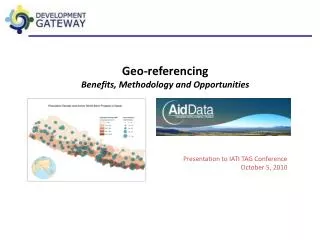
Geo-Referencing of Scans. Oliver Bürkler Technical Product Manager May 2010. Geo-Referencing of Scans Laser Scanner Training – Europe –. Training Objectives: Difference between local registration and geo-referenced registration Typical coordinate systems for geo-referencing

E N D
Geo-Referencingof Scans Oliver Bürkler Technical Product ManagerMay 2010
Geo-Referencing of Scans Laser Scanner Training – Europe – • Training Objectives: • Difference between local registration and geo-referenced registration • Typical coordinate systems for geo-referencing • How to do get a geo-referenced registration in Scene • What does “Traversing” mean?
Geo-Referencing of Scans Laser Scanner Training – Europe – • Positioning the Scanner • The scanner will record only what it can „See“ • This means that the references and the target object must be in the line of sight of the unit. • For registration each scan requiresa minimum of 3 visible references • These references should be evenly spaced around the scanner. For better control it is better to use 4 references per scan.
Geo-Referencing of Scans Laser Scanner Training – Europe – Automatic Target Identification • Reference Targets • The FARO references are normally • Spheres and Paper targets • References should be • Easily visible • Spaced 2 to 15 from the scanner(depending on size and resolution) • Secure Starter Kit SuperSpheres Checker Board Circular Flat
Geo-Referencing of Scans Laser Scanner Training – Europe – • Local Registration • One scan serves as origin of thecoordinate system • This “Reference Scan” isdefined • Randomly by Scene (default)or • Manually by the user Reference Scan
Geo-Referencing of Scans Laser Scanner Training – Europe – Geo-Referenced Registration
Geo-Referencing of Scans Laser Scanner Training – Europe – • Geo-Referenced Registration • A surveyor is providing the coordinates of the reference targets based on a geodetic coordinate system • Normally, the coordinates are determined with • Total Stations – or – GPS systems
Geo-Referencing of Scans Laser Scanner Training – Europe – • Geodetic Coordinate Systems • Land surveying is a very old technology • Traditionally, mathematical calculation capabilities have been very limited • Until today, surveyors are working in 2-dimensional coordinate systems • The surface of the earth is assumed to flat • Coordinates are often given as “Easting and Nording” or “Right and Up” (German: “Rechtswert und Hochwert”) • Then, after defining the 2-dimensional position on the earth surface, a height information is added • The height is determined independently from the position and is typically less accurate
Geo-Referencing of Scans Laser Scanner Training – Europe – • Geodetic Coordinate Systems • Unfortunately… • …the earth is not flat!
Geo-Referencing of Scans Laser Scanner Training – Europe – • Geodetic Coordinate Systems • …therefore geodetic coordinate systems are trying to provide detours to avoid 3D and a curved surface. • Many common coordinate systems are based on the UTM system • UTM means “Universal Transverse Mercator” which is a geometrical transformation projecting each point on the global ellipsoid onto a flat plane • To make this work, the globe is cut into “zones” of 6° width • As mathematical model of the earth´s shape the so-called WGS84 or GRS80 ellipsoid is used
Geo-Referencing of Scans Laser Scanner Training – Europe – • Geodetic Coordinate Systems • Principle of UTM transformations
Geo-Referencing of Scans Laser Scanner Training – Europe – • Geodetic Coordinate Systems • Global “Zones”
Geo-Referencing of Scans Laser Scanner Training – Europe – • Geodetic Coordinate Systems • UTM zones for Europe
Geo-Referencing of Scans Laser Scanner Training – Europe – • Geodetic Coordinate Systems • But this is not everything: • Military is using a UTM system as well, but with a different grid subdivision (100km x 100km grid size). This is called Military Grid Reference System (MGRS) • Germany, for example, is using a system called “Gauss-Krüger” named according the mathematician Carl Friedrich Gauss and Johann Heinrich Louis KrügerThis uses the same mathematical transformations, but a Bessel or Krassowski ellipsoid and 3° wide zones • GPS systems are using longitudinal and latitudinal coordinates based on the WGS84 or GRS80 ellipsoid (note: also the height is missing here and needs to be specified separately)
Geo-Referencing of Scans Laser Scanner Training – Europe – • Geo-Referencing in Scene • Independent from the used coordinate system, what you need is a list of coordinates from the surveyor: • ASCII file format (file extension *.txt or *.cor) • One coordinate per line • Point name -comma- X coordinate -comma- Y coordinate -comma- Z coordinate • “Point” as decimal separator • Example: A,146.445675591,-6.8416812176,0.12194667699 B,142.674728212,-2.9329090693,-0.14458280531 C,139.682633752,4.3632461477,0.0004202706739 D,153.66088266,0.47645329791,-0.021972010218 E,148.270912355,5.4490686746,-0.13309600625 F,134.643476,-14.297264,0.089182
Geo-Referencing of Scans Laser Scanner Training – Europe – • Geo-Referencing in Scene • Things to be aware of: • Keep the coordinates within “kilometer range” • Scene will have difficulties in 3D view if the coordinates become too large • Typical surveyor coordinates are too large!I.e. the coordinate of the city of Dresden, Germany in UTM (WGS84) is: • Zone 33-North • Easting 411.777,6 m • Nording 5.655.984,3 m • Tell the surveyor, to cut away all leading digits which do not change(if necessary they can be added as a global transformation to the Workspace again)
Geo-Referencing of Scans Laser Scanner Training – Europe – • Geo-Referencing in Scene • Things to be aware of: • Make sure the surveyor gives the coordinates in the correct, mathematical sequence • Sometimes surveyors use tell the up value first and then the right value • If you import this into Scene, the scans will be rotated by 90°
Geo-Referencing of Scans Laser Scanner Training – Europe – • Geo-Referencing in Scene – Workflow – • Create your workspace as usual (import scans, filter etc.) • Import the coordinate file from the surveyor • Drag & Drop the file into Scene • Use “File – Import” to import the coordinate file • Scene should automatically create the Folder “References”.For each coordinate from the file, there should be a point object.Each point will have to coordinates given by the file • Run the normal scan placement process • Detect targets if not done yet • “Place scans” • Scene will automatically identify the suitable survey coordinates from the geometrical pattern of targets. • Target names will be derived from point numbers given by the coordinate file
Geo-Referencing of Scans Laser Scanner Training – Europe – • “Traversing” in Scene – Workflow – • “Traversing” is a common surveyor technique where the instrument (total station or scanner) is placed on top of a known coordinate. • This technique helps to minimize the amount of targets. The scanner position is known, the inclination sensor forces the scan to be leveled. • Only one additional target is needed • This target is typically placed on another tripod of which the position is also known • Depending on whether this target is in front or behind you (seen from the scanning workflow), it is called front-sight or back-sight in surveyor-slang
Geo-Referencing of Scans Laser Scanner Training – Europe – • “Traversing” in Scene – Workflow – • Scene is capable of doing this (it´s just a special case of geo-referencing): • Each scan needs to have a point object with the coordinate 0,0,0 (= scanner origin) which has the same name as the scan itself. • Coordinate import and scan placement works as usual.You just need to make sure that the coordinate file consists of coordinates for the scanner position (naming!) • Scene will make sure that scan gets exactly the given position • If there are tensions in the calculation, they will appear at the reference targets