Download
1 / 18
180 likes | 328 Views
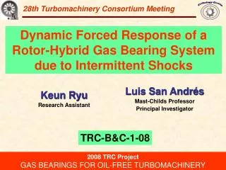
29th Turbomachinery Consortium Meeting. Dynamic Response of a Rotor-Air Bearing System due to Base Induced Periodic Motions. Luis San Andrés Mast-Childs Professor Principal Investigator. Yaying Niu Research Assistant . TRC-B&C-1-09. 2009 TRC Project

E N D
29th Turbomachinery Consortium Meeting DynamicResponse of a Rotor-Air Bearing System due to Base Induced Periodic Motions Luis San Andrés Mast-Childs Professor Principal Investigator Yaying Niu Research Assistant TRC-B&C-1-09 2009 TRC Project GAS BEARINGS FOR OIL-FREE TURBOMACHINERY Start date: Oct 1st, 2008
Micro Turbomachinery (< 0.5 MW) Turbo Compressor 100 krpm, 10 kW Advantages • Compact and fewer parts • Portable and easily sized • High energy density • Lower pollutant emissions • Low operation cost http://www.hsturbo.de/en/produkte/turboverdichter.html Micro Turbo 500 krpm, 0.1~0.5 kW Oil-free turbocharger 120 krpm, 110 kW http://www.miti.cc/new_products.html http://www.hsturbo.de/en/produkte/micro-turbo.html
Gas Bearings for MTM Advantages Metal Mesh Foil Bearing • Small friction and power losses • Less heat generation • Simple configuration • High rotating speed (DN value>4M) • Operate at extreme temperatures Issues • Small damping • Low load carrying capacity • Prone to instability GT 2009-59315 Gas Foil Bearing Flexure Pivot Bearing AIAA-2004-5720-984 GT 2004-53621
Gas Bearings for MTM GT 2009-59199 2008: Intermittent base shock load excitations Drop induced shocks ~30 g. Full recovery within ~ 0.1 sec. Ps=2.36 bar (ab) Rotor motion amplitude increases largely. Subsynchronous amplitudes larger than synchronous. Excitation of system natural frequency. NOT a rotordynamic instability!
2008-2009 Objectives Evaluate the reliability of rotor-air bearing systems to withstanding base load excitations • Set up an electromagnetic shaker under the base of test rig to deliver periodic load excitations • Measure the rig acceleration and rotordynamicresponses due to shaker induced excitations • Model the rotor-air bearing system subject to base motions and compare the predictions to test results
2009 Gas bearing test rig The rod merely pushes on the base plate!
Test rotor and gas bearings Flexure Pivot Hybrid Bearings:Improved stability, nopivot wear. Rotor • 0.825 kg in weight • 190 mm in length • Location of sensors and bearings noted Gas bearing Clearances ~42 mm, Preload ~40%.Web rotational stiffness = 62 Nm/rad. Test rig tilts by 10°.NOTLoad-on-Pad (LOP) !
Shaker delivered accelerations Rotor speed: 34 krpm (567 Hz) Due to electric motor Shaker transfers impacts to the rig base! Super harmonic frequencies are excited.
Rotor speed coast down tests No base excitation Ps = 2.36 bar (ab) Rotor coasts down from 35 krpm No added imbalance Slow roll compensated Synchronous response Subsynchronous whirling starts beyond 30 krpm, fixed at system natural frequency 193 Hz Pressure 2.36bar 3.72bar 5.08bar Natural Freq 192Hz 217Hz 250Hz
Rotor speed coast down tests Ps = 2.36 bar (ab) Shaker input frequency: 12Hz • Subsynchronous response: • 24 Hz (Harmonic of 12 Hz) • Natural frequency 193 Hz Synchronous Dominant! Excitation of system natural frequency does NOT mean instability!
Fixed speed, increasing pressures Shaker input frequency: 12Hz Rotor speed: 34 krpm (567 Hz) 12Hz, 24Hz, 36hz, etc NOT due to base motion! Pressure increases 243Hz 215Hz Offset by 0.01 mm 193Hz Rotor response amplitude at the system natural frequencydecreases, as the feed pressureincreases.
Fixed pressure, increasing speeds Shaker input frequency: 12Hz Feed pressure: 2.36 bar (ab) 12Hz, 24Hz, 36hz, etc Speed increases 193Hz 180Hz 180Hz Rotor response amplitude at the system natural frequencyincreases, as the rotor speedincreases.
Fixed speed and pressure, increasing input frequency Rotor speed: 34 krpm (567Hz) Feed pressure: 2.36 bar (ab) 193Hz Frequency increases NOT due to base motion! Same excitation magnitude for 6, 9, and 12 Hz Rotor response amplitude at the system natural frequencyincreases, as the input frequencyincreases.
XLTRC2 prediction FE rotor model Shaker input frequency: 12Hz Feed pressure: 2.36 bar (ab) System Natural Freq Conical XLTRC2 Cylindrical Measured Input acceleration in XLTRC2, simulate actual acceleration. XLTiltPadHGB™ Prediction uses synchronous speed bearing force coefficients. In actuality, gas bearing force coefficients are frequency dependent!
XLTRC2 prediction Shaker input frequency: 12Hz Feed pressure: 2.36 bar (ab) Rotor speed: 34 krpm (567 Hz) Input acceleration only on VERTICAL direction Measured N.F. component Predicted natural frequency component Prediction frequency step: 1.25 Hz. XLTRC2 predicts absolute rotor motions! Measured rotor response is relative to bearing housing.
Rigid rotor model prediction Rotor 1st bending mode: 1,917 Hz (115 krpm) Equations of Motion: Shaker input frequency: 12Hz Feed pressure: 2.36 bar (ab) Steady-State! Absolute rotor response Relative rotor response Input acceleration in rigid rotor model, VERTICAL direction only! System Natural Frequency: Rigid rotor model XLTRC2 Measured System response equals to the superposition of unique single frequency responses.
Rigid rotor model prediction Shaker input frequency: 12Hz Feed pressure: 2.36 bar (ab) Rotor speed: 34 krpm (567 Hz) Measured N.F. component Above the natural frequency, the system is isolated! Predicted natural frequency component Relative rotor motion Rigid rotor model predicts relative rotor motions! The test rotor-bearing system shows good isolation.
Conclusions • The recorded rotor response contains the main input frequency (5-12 Hz) and its super harmonics, and the rotor-bearing system natural frequency. • The motion amplitudes at the natural frequency are smaller than the components synchronous with rotor speed. • The rotor motion amplitude at the system natural frequencyincreases as the gas bearing feed pressure(5.08~2.36bar) decreases, as the rotor speed (26~34krpm) increases, and as the shaker input frequency (5~12 Hz) increases. • Predicted rotor motion responses obtained from XLTRC2® and an analytical rigid rotor model show good correlation with the measurements. The system shows reliable isolation. Reliability of rotor-air bearing system to withstanding base load excitations demonstrated