Download
1 / 36
360 likes | 464 Views
6 th CLIC Advisory Committee. Damping Ring issues Overall optimization, low emittance tuning and other beam tests. Yannis PAPAPHILIPPOU CERN. February 2 nd , 2011. Acknowledgements.

E N D
6th CLIC Advisory Committee Damping Ring issuesOverall optimization, low emittance tuning and other beam tests Yannis PAPAPHILIPPOU CERN February 2nd, 2011
Acknowledgements • F. Antoniou, M. Barnes, S. Calatroni, P. Chiggiatto, R. Corsini, A. Grudiev, E. Jensen, E. Koukovini-Platia,T. Lefevre, G. Rumolo, S. Russenchuck, H. Schmickler, D. Schoerling, D. Schulte, M. Taborelli, G. Vandoni, F. Zimmermann (CERN) • S. Casalbuoni, A. Muller, A. Bernhard, E. Huttel, P. Peiffer, R. Rossmanith (KIT/ANKA), • M. Boland, R. Dowd, R. Rassool, E. Tan, K. Wooton (ACAS) • A. Bragin, E. Levichev, D. Shatilov, S. Siniatkin, S. Piminov, P. Vobbly, K. Zolotarev (BINP) • B. Podobedov (BNL) • F. Toral (CIEMAT) • M. Billing, J. Calvey, J. Crittenden, G. Dugan, M. Palmer, D. Rubin, J. Shanks (Cornell) • M. Wendt (FNAL) • A. Faus-Golfe (IFIC-Valencia) • D. Alesini, M. Biagini, S. Guiducci, P. Raimondi (INFN-LNF) • S. Smith (SLAC) • R. Bartolini (DIAMOND) • K. Kubo, T. Naito, J. Urakawa (KEK-ATF) • E. Wallen, A. Anderson (Maxlab) • M. Boege, L.Rivkin, A. Streun (PSI-SLS)
Outline • Progress since last ACE • Answers to committee’s concerns • DR parameter optimisation • Layout • Lattice and Dynamic Aperture • Collective effects • Wiggler design • Wiggler modelling and prototyping • Power absorption studies • RF design • Delay loop and RF deflector considerations • Kicker design • Low emittance tuning • Future plans • Experiments in storage rings • LER collaboration ACE 2011
From ACE Answers Damping Ring • Concerns • Space charge tune shift (0.2) very large, • Space charge tune-shift reduced to ~0.1 with combined reduction of circumference and increase of bunch length (see Giovanni’s talk) • 2GHz RF system seems very hard. No detailed calculation or simulation seem available. • Conceptual design of both 1 and 2GHz system done (see Alexej’s talk) • 1GHz system adopted as baseline (much closer to existing RF designs) but train interleaving necessitates delay loop • Stability of RF deflector should not be an issue (experience in CTF3) • Beam pipe diameter very small (10mm). • The beam pipe radius is 10mm, and the wiggler gap is 13mm • Bunch length very short (1mm). • Bunch length was increased to almost 2mm (see above) • HOM power studies not available. • On-going work (see Giovanni’s Talk) • Impedance estimation for certain components is done or under way (RF, kickers, absorbers, wigglers)
From ACE Answers Damping Ring, continued • Concerns / Suggestions • Large gap in the ring might cause a lot of difficulties for the RF system and beam stability requirements. • Synchronous phase spread due to the gap transient is missing. • Gap reduced to half for 1GHz RF frequency (two trains) • Various concepts of beam loading compensation elaborated (see Alexej’s talk) • No studies made on single and multi bunch instabilities. • Feedback requirements missing. • Evaluation of all possible single bunch and multi-bunch instabilities, establishing transverse and longitudinal impedance budgets exists since 2009, including feedback requirements • First simulation studies performed (see Giovanni’s talk) • Longitudinal dynamics (with RF cavities) has to be checked. • On-going work (see Alexej’s talk) • Committee feels that not enough data presented to judge the DR feasibility. • DR is one of the major performance drivers for any LCs. • Three presentations addressing major issues foreseen this time
From ACE Answers Damping Ring, continued • Possibly into TDR • Ideally a DR modeling that includes everything should be developed and applied to the present DR design before the CDR deadline. This might not be possible given the lack of time and resources, in that case it might be risky to claim feasibility in the CDR. • All effects are at least evaluated through scaling and major performance issues are addressed with detailed simulations (within the limited time and resources) • DR design remains demanding with various beam dynamics and technology challenges • Large network of collaboration established within the Low Emittance Rings community in order to share experience, design approaches, tools and perform common experimental work in storage rings and test facilities
DR parameter optimization • Reduced circumference by 15% • Lower space-charge tune-shift and relaxed collective effects • Decreased dipole field by 25% (cell length increased by 5%) • Lower energy loss per-turn for reducing RF stationary phase • Doubled momentum compaction factor • Longer bunch for reducing space-charge tune-and increasing CSR instability threshold • Considered RF frequency of 1GHz (2 trains) • Half peak power/current and harmonic number, thereby reducing transient beam loading and bunch length • Less e-cloud production due to double bunch spacing • Less pronounced Fast Ion Instability • Train recombination in a delay loop
e- linac to PDR transfer line X-ray dump e- Pre-damping Ring X-ray dump X-ray dump e- PDR to DR transfer line e- Damping Ring X-ray dump e- DR to Booster linac transfer line Damping Rings Complex layout Delay loop e+ DR to Booster linac transfer line X-ray dump e+ Damping Ring e+ PDR to DR transfer line X-ray dump X-ray dump e+ Pre-damping Ring X-ray dump e+ linac to PDR transfer line
DR layout • Racetrack shape with • 96 TME arc cells (4 half cells for dispersion suppression) • 26 Damping wiggler FODO cells in the long straight sections (LSS) • Space reserved upstream the LSS for injection/extraction elements and RF cavities • Circumference reduced (30% less wigglers) ACE 2011
S. Sinyatkin, F. Antoniou Arc cell • 2.51m-long TME cell with bends including small gradient (as in NLC DR and ATF) • Phase advances of 0.401/0.05 and chromaticities of -1.5/-0.5 • IBS growth rates reduced due to optics function inversion • Dipole length lengthened for reducing energy long/turn and RF stationary phase ACE 2011
Wiggler cell and Dispersion suppressor S. Sinyatkin, F. Antoniou • LSS filled with wiggler FODO cells of around ~6m • Horizontal phase advance optimised for minimizing emittance with IBS, vertical phase advance optimised for aperture • Drifts of 0.6m downstream of the wigglers (more length for absorbers, vacuum equipment and instrumentation) • Dispersion suppressors re-designed adding space for RF cavities and beam transfer elements
Dynamic Aperture F. Antoniou • Tracking with chromatic sextupoles and misalignments • Very large DA translated to around +/- 5mm in both place for on-momentum • Further DA optimisation on-going • Working point, magnet errors, wiggler effect
Space-charge reduced <0.1 with combined circumference reduction and bunch length increase Intrabeam scattering simulated showing excellent agreement with theory Parameter choice (energy, optics,…) for minimizing the growth e-cloud in the e+ DR imposes limits in PEY (99.9%) and SEY (<1.3) achieved with wiggler absorption scheme and chamber coatings (amorphous carbon) Fast ion instability in e- DR constrains vacuum pressure to around 0.1nTorr Single bunch instabilities avoided with smooth vacuum chamber design Simulations for instability thresholds for resistive wall Resistive wall coupled bunch controlled with feedback Impedance estimates for effect of multiple material layers G. Rumolo’s talk Collective effects
Stronger wiggler fields and shorter wavelengths necessary to reach target emittance due to strong IBS effect Stronger field and moderate wavelength reduces IBS effect while reaching target emittance Current density can be increased by different conductor type Nb3Sn can sustain higher heat load (~10 times higher than NbTi) Two wiggler prototypes 2.5T, 5cm period (CERN/BINP) 2.8T,4cm period, (CERN/KIT) Mock-ups magnetically tested To be installed in storage ring for beam measurements F. Antoniou Wigglers’ effect with IBS 500nm limit
D. Schoerling, S. Russenchuck, et al. Nb-Ti Technology Nb3Sn Technology CDR SCU14 in ANKA TDR DEPENDING ON APPROVED FUNDING!
NbTi wiggler ACE 2011
Radiation absorption scheme K. Zolotarev, D. Schoerling A 4-wigglers scheme • Gap of 13mm (10W/m) • Combination of collimators and absorbers (PETRAIII type, power density of up to 200W/cm) • Terminal absorber at the end of the straight section (10kW) ACE 2011
A. Grudiev’s talk RF system • RF frequency of 2GHz • Single train of 312 bunches spaced at 0.5ns • R&D needed for power source • High peak and average power introducing transient beam loading to be handled by LLRF system • The 1GHz frequency was chosen as baseline • Two trains of 156 bunches spaced at 1ns • Eases beam dynamics (e.g. e-cloud) • Drives the RF system to more conventional parameters for power source and LLRF • Complication with train recombination (to be studied and tested in CTF3) • Conceptual design for RF system including LLRF performed for both frequencies • Scaling for both frequencies suggest that total transverse impedance is ~10 times below threshold ACE 2011
Delay loop considerations Delay loop RF deflector 1GHZ • Unique α-shape loop (as in CTF3) for both species and circumference of ~260m, i.e. half of the damping rings • Optics tuned to achieve high-order iso-chronism • TME cells and sextupole tuning • Emittance growth due to synchrotron radiation • Negligible (low energy and relatively short length) • Path length very critical (+/-3mm in CTF3) • Wiggler, orbit correctors and optics tuning for correction • Systematic energy loss is roughly ~half of the DR • Corrected with RF cavities of a few hundred kV.
RF deflector • Stability of RF deflector for keeping (horizontal) emittance growth small (<10% of the beam size) • Deflection tolerance of ~10-3 • More relaxed for larger beam sizes and lower septum thickness • Within reach of klystrons • Need simulations to further refine tolerances (especially for phase error) • Experience with the CTF3 RF deflectors instrumental
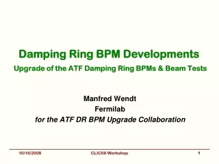
Kicker design M. Barnes • Kicker jitter tolerance ~ few 10-4 • Double kicker system relaxes requirement • 3.3 reduction achieved @ATF • Striplines required for achieving low longitudinal coupling impedance • Significant R&D needed for PFL (or alternative), switch, transmission cable, feed-throughs, stripline, terminator • Prototyped under the Spanish Program “Industry for Science” • Collaboration is set-up with ATF for beam tests ACE 2011
Low emittance tuning • Present alignment tolerances not far away from ones achieved in actual storage rings • Light source community and ATF hold present record of vertical emittance • A collaboration with SLS is financed through EU (TIARA) • MOU signed with ASLS (PhD student, MD time) • MOU to be signed with DIAMOND ACE 2011
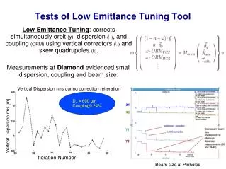
Reaching Quantum Limit Of Vertical Emittance SLS achieves in routine operation εy = 2.4pm Tousheck lifetime variation with RF voltage in ASLS corresponding toεy = 1.24 ± 0.3pm Beam size measurement in Diamond after coupling correction (down to 0.08%) gives εy = 2.2 ± 0.4pm E.Tan, R. Dowd, R. Bartolini, IWLC 2010
DR technology and experimental program • Super-conducting wigglers • Demanding magnet technology combined with cryogenics and high heat load from synchrotron radiation (absorption) • High frequency RF system • 1.5GHz RF system in combination with high power and transient beam loading • Coatings, chamber design and ultra-low vacuum • Electron cloud mitigation, low-impedance, fast-ion instability • Kicker technology • Extracted beam stability • Diagnostics for low emittance • Profile monitors, feedback system • Experimental program set-up for measurements in storage rings and test facilities • ALBA (Spain), ANKA (Germany), ATF (Japan), Australia Synchrotron (Australia), CESRTA (USA), SOLEIL (France),…
Low Emittance Rings collaboration • Initiated by the ILC-CLIC working group on damping rings • Workshop organized in January 2010 at CERN identifying items of common interest among the low emittance rings community (synchrotron light sources, linear collider damping rings, b-factories) • Low emittance rings working groups formed • A EU network proposal is under approval (ESGARD) • Interest from 25 institutes worldwide • Next workshop to be organized during 2011 ACE 2011
Reserve slides ACE 2011
PDR design F. Antoniou, CLIC09 Main challenge: Large input emittances especially for positrons to be damped by several orders of magnitude Design optimization following analytical parameterization of TME cells Detuning factor (achieved emittance/TME)> 2 needed for minimum chromaticity Target emittance reached with the help of conventional high-field wigglers (PETRA3) Non linear optimization based on phase advance scan (minimization of resonance driving terms and tune-shift with amplitude) ACE 2011
DRchallenges and adopted solutions • High-bunch density • Emittance dominated by Intrabeam Scattering, driving energy, lattice, wiggler technology choice and alignment tolerances • Electron cloud in e+ ring imposes chamber coatings and efficient photon absorption • Fast Ion Instability in the e- ring necessitates low vacuum pressure • Space charge sets energy, circumference limits • Repetition rate and bunch structure • Fast damping achieved with wigglers • RF frequency reduction considered due to many challenges @ 2GHz (power source, high peak and average current) • Output emittance stability • Tight jitter tolerance driving kicker technology • Positron beam dimensions from source • Pre-damping ring challenges (energy acceptance, dynamic aperture) solved with lattice design ACE 2011
DR arc cell and IBS S. Sinyatkin, et al., EPAC 2009 • Increasing space, reducing magnet strengths • Reducing chromaticity, increasing DA • IBS growth rates reduced, i.e. zero current equilibrium emittance increased but IBS dominated emittance not changed • Combined function bends with small gradient (as in NLC DR and ATF) ACE 2011
1 vs. 2GHz for PDR • Larger bunch spacing (1 vs. 0.5 nm) halves harmonic number (1326 vs. 2581), and increases momentum acceptance by 40% (1.7 vs. 1.2%), thereby making the capture efficiency of the positron beam even better • For keeping the same momentum acceptance, the RF voltage can be reduced (~10 vs. 6.8MV) • All the rest of the parameter changes are as the same as for the damping rings
1 vs 2GHZ for DR (I) • In the DRs, the harmonic number reduction, raises the equilibrium longitudinal emittance (bunch length). • In order to keep it to the same level (IBS effect), the RF voltage should be increased reducing stationary phase (RF bucket becomes more linear). • For shorter ring (space charge reduction), stationary phase gets increased (quite big for 2GHz), i.e. voltage should be increased and momentum compaction factor reduced (relaxing arc cell focusing) • Extraction kicker rise time becomes smaller but it is still long enough (620-670ns). This might eliminate the possibility to use IGBT switches. • The 2-train structure may require two separate extraction kicker systems (two pulses of equal size and flat top of 160ns as in the present case) or one kicker with a longer flat top (1μs). • RF frequency of 1GHz is closer to existing high-power CW klystron systems used in storage rings or designed for NLC damping rings (714MHz). An extrapolation of this design should be straightforward. • Larger bunch spacing reduces peak current and power by a factor of 2 (beam loading reduction)
1 vs 2GHZ for DR (II) • The e-cloud production and instability is reduced with the larger bunch spacing. • In the e- rings, the fast ion instability will be less pronounced due to the larger bunch spacing by doubling the critical mass above which particles get trapped (not allowing the trapping of H2O+ and probably CO+). The reduced number of bunches per train will reduce the central ion density, the induced tune-shift and will double the rise time of the instability, thus relaxing the feedback system requirements. • A bunch-by-bunch feedback system is more conventional at 1 than at 2 GHz
Kicker stability • Kicker jitter is translated in a beam jitter in the IP. • Typically a tolerance of σjit ≤0.1σxis needed • Translated in a relative deflection stability requirement as • For higher positions at the septum (larger injected emittances or lower beta functions) the stability tolerance becomes tighter • The tolerance remains typically to the order of 10-4 • Available drift space has been increased to reduce kicker voltage spec. ACE 2011
Kicker Impedance Allowable transverse broad band beam impedance, in the CLIC PDR & DR, is 10MΩ/m. Maximum transverse impedance per kicker system is assumed to be 2%, i.e. 200kΩ/m. Damping Ring Calculated transverse impedance, for 1.3m long striplines, is less than 200kΩ/m, for all frequencies, with or without tapers. Calculated transverse impedance, for 3m long striplines, is less than 200kΩ/m, for all frequencies, with or without tapers. For longitudinal impedance reasons, two sets of striplines with individual length of 1.5m may be used. Transverse impedance of two sets of 1.5m striplines would be slightly greater than twice that shown for 1.3m striplines. Thus each PDR kicker system would meet the transverse impedance specification. PreDamping Ring M. Barnes
Damping Rings diagnostics • Turn by turn transverse profile monitors (X-ray?) with a wide dynamic range: • Hor. geometrical emittance varies from 11nm.rad @ injection to 90pm.rad @ extraction and the vertical from 270pm.rad to 0.9pm.rad. • Capable of measuring tails for IBS • This would probably be the most challenging item • Longitudinal profile monitors • Energy spread of 0.5% to 0.1% and bunch length from 10 to 0.1mm. • Note that the dispersion around the ring is extremely small (<12mm). • Fast beam loss monitoring and bunch-by-bunch current measurements • E-cloud + ion diagnostics • 300PUs, turn by turn (every 1.6μs) • 10μm precision, forlinear and non-linear optics measurements. • 2μm precision for orbit measurements (vertical dispersion/coupling correction + orbit feedback). • WB PUs for bunch-by-bunch (bunch spacing of 0.5ns for 312 bunches) and turn by turn position monitoring with high precision (~2μm) for injection trajectory control, and bunch by bunch transverse feed-back. • PUs for extraction orbit control and feed-forward. • Tune monitors and fasttune feed-back with precision of 10-4, critical for resolving instabilities (i.e. synchrotron side-bands, ions) ACE 2011