Download
1 / 25
250 likes | 335 Views
Test Facility Experimental Program ILC Division RD report June 12, 2006 Marc Ross. ATF2 cavity BPMs ATF nanoBPM system - nanoGrid ATF2 Movers TTF HOM – dipole / monopole ESA/LCLS bunch length ILCTA. ATF2 Cavity BPM.

E N D
Test Facility Experimental ProgramILC Division RD reportJune 12, 2006Marc Ross ATF2 cavity BPMs ATF nanoBPM system - nanoGrid ATF2 Movers TTF HOM – dipole / monopole ESA/LCLS bunch length ILCTA
ATF2 Cavity BPM • SLAC group will provide the full cavity system from the hybrid combiner to data server • 70 + channels • Beam tests April 10 – 22. • Single ATF2 cavity between the two triplets (no mover) • First look is ‘good’ • Data analysis started • Full system delivery delayed • (was to have been June 5) – delay is mid-August. • Following discussions with group at ATF2 meeting • Our first cavity BPM System • Test result documentation (acceptance) • Mechanical • Calibration algorithm Marc Ross - SLAC
ATF2 Cavity BPM Production electronics • 6 GHz receiver board layout • Realistic system design including packaging and mounting hardware • Tested successfully at ATF April 2006 Marc Ross - SLAC
System design Local configuration
Beam Tests of ATF2 electronics (Y. Honda) Marc Ross - SLAC
Beam Tests Marc Ross - SLAC
Beam Tests Marc Ross - SLAC
Schedule Marc Ross - SLAC
Do the Nanogrids Help? Data from 13 April 2006 at 22:56: • 96 events at nominal position • 64 events at +/-20 microns to calibrate • Resolution, no nanogrids 19.1 nm • Resolution, with nanogrids 15.6 nm Marc Ross - SLAC
ATF Laserwire • extraction line near old Compton IP • requires special optics • need wire scanner to confirm • backup lens – real one delayed and lost in the mail (Oxford) • now testing fully corrected lens for operation in November • two graduate students to be posted at ATF all year • Miryam Qureishi (Oxford) and Lawrence Deacon (RHUL) • Guidance from Pavel Karataev (RHUL) Marc Ross - SLAC
ATF laser – wire scan (May 25) • First scans • Optics and laser aberrations • (factor 10 scale error) σ = 17.6 +/- 0.4 µm Marc Ross - SLAC
ATF2 Mover System Marc Ross - SLAC
Mover shipping and requirements: Marc Ross - SLAC
TTF HOM studies – plan for August • Goals: • install and commission the HOM BPM DOOCs server • beam tests of HOM SVD algorithm • fast processor HOM board (FNAL) • HOM phase feedback • 7 shifts; 2 weeks of beam time July 28 to August 13 • A lot of time allocated • 3 DESY, 5 Fermilab, 2 SLAC, 2 Saclay staff, ANL, JLab, Cockroft. • Steve Molloy (SLAC) and Nathan Eddy (Fermi) working on analysis Marc Ross - SLAC
Phase Measurement from Monopole modes • Phase of monopole modes determined by beam phase. • Use fast (5GS/s, 6GHz BW) scope directly measuring HOM signals • Compare HOM monopole phases with 1.3 GHz reference • Not completely straightforward since TTF trigger jitter > 1 cycle of 1.3GHz • Plot phase vs. machine cycle for TM011-7 and TM011-8, and phase difference between modes • Note: measurent uses “accidental” data, taken during other experiment, not optimized. Marc Ross - SLAC
Higher Order Monopole Modes • 2300 – 2500 MHz • Both couplers for 1 cavity shown • 0.1 degree (L-band) precision 0.2 ps Note that different lines have different couplings to the 2 couplers Monopole lines due to beam, and phase is related to beam time of arrival Fundamental 1.3GHz line also couples out – provides precise RF to beam phase for control Marc Ross - SLAC
Beam Phase vs. RF Measurement During 5 Degree Phase Shift 2 cavities, same structure give 0.34 degree L-band RMS phase difference Measure 5 degree phase shift commanded by control system Marc Ross - SLAC
What is System Resolution, Drift Compare 2 couplers on same cavity, RMS difference 0.12 degrees L-band. Electronics noise ~0.08 degrees cavity to cavity difference (0.3 degrees may be due to microphonics) Compare 2 cavities for long (7 hour) run. RMS difference 0.69 degrees L-band. Combination of electronics drift and cavity to cavity phase shifts. Marc Ross - SLAC
Summary of Phase System Performance • System noise ~0.08 degrees L-band, 1 minute timescales. • Also measured ~0.1 degree for 10 minutes • Cavity to cavity difference ~0.3 degrees, possibly microphonics. • Drift <0.7 degrees over 7 hours – probably dominated by real cavity to cavity variations. • Cable length change of 10 degrees results in <0.25 degree (consistent with 0) change in measured phase Marc Ross - SLAC
ESA/LCLS bunch length monitor • This is a ‘single-pass’ device – intended as a ‘relative’ monitor to complement LOLA • Two devices to be built for LCLS BC1 • Deadline November 2006 • Testing until November 2007 • ‘CSR’ or focused wave (BL11) and gap monitor (BL12) • Both may use pyroelectric devices • Beam tests in ESA this month • Accurate mm-wave measurements are difficult • Full system relies on integration with LOLA (29-4) • No LOLA in ESA Marc Ross - SLAC
BL12 Bunch Length Monitor • Located just after the BL11 monitor • Uses gap and diode detectors • Only vacuum component is conventional ceramic gap • Initially instrument with 100GHz diodes • Add higher frequency diodes as needed • Diodes used in pairs to reduce effect of beam motion • 20cm waveguide used to disperse pulse (~1ns), keep peak power reasonable on diodes. • 20dB gain horns on diodes Marc Ross - SLAC
BL12 Marc Ross - SLAC
BL12 Development Plan • Similar diodes operating at 100GHz have been tested in End Station B. • Additional test in end station B in April 2006, using same electronics as LCLS • Will use pair of diodes to check measurement noise. • Initial test in LCLS will be done with a pair of 100GHz detectors. • As shorter bunch length measurements are required, additional diodes and waveguide can be added • Use of optical breadboard makes installation of new diodes (on optical clamp mount) straightforward. • Will try using a pyroelectric detector mounted next to the gap. • Should be able to measure total mm-wave power, and compare with toroid current measurement to get bunch length signal • Very simple and inexpensive system if it works. • In principal extends to very short bunch lengths • Must be calibrated with LOLA Marc Ross - SLAC
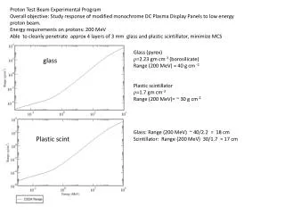
ESA Bunch Length Monitor simple ceramic gap and diode detector diode and waveguide form crude bandpass filter 200 to 400 um bunch length sensitivity (ILC) Two 100 GHz detectors track with RMS error of 1.5% 100GHz Diode, WR10 waveguide and horn WR10 and WR90 waveguides at ceramic gap Marc Ross - SLAC
Summary – ongoing work and developments since April 2006 • ATF cavity BPM’s (UK, UCB, LLNL, KEK) • Near a spectrometer result with 2 triplets+1 (?) • Nanogrid tests – first results • ATF2 BPM cavities (Pohang, KEK, UCL) • 1/3 copper cavities done • Electronics delayed 2 months system issues • ATF extraction kicker (LLNL, KEK) delivered in June • To be used in September 2006 • TTF HOM (DESY, KEK, Saclay, FNAL) • System implementation in August • Phase measurements excellent (April 21) • LCLS BLM • first results in May