Download
1 / 103
1.04k likes | 1.1k Views
RiccoTek shares the document about the SNL Plummer Block Housings. Know more at: http://www.riccotek

E N D
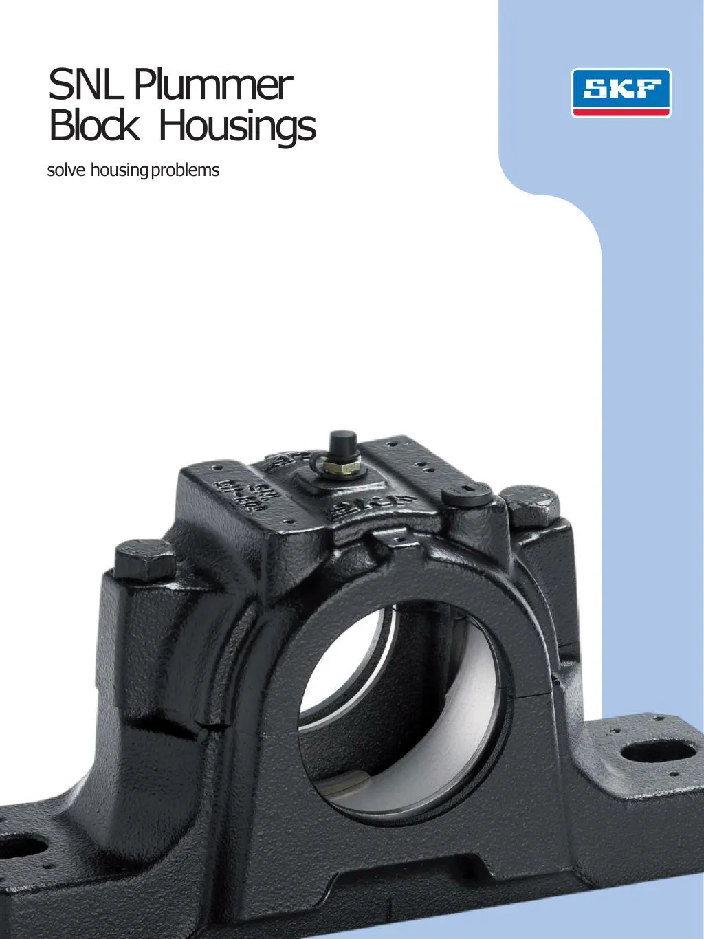
SNL Plummer Block Housings solve housingproblems
Contents A C Productinformation Productdata TheSKFbrand nowstands formore than ever before, and means more toyouasavaluedcustomer. 3 Fewer bearing replacementsandless maintenance Plummer block housingshavemuch tooffer SNL plummer block housingshave more tooffer One basic design –manyvariants Features andbenefits Superior performance in allsectors 50 Designations and housing data – general 50 Designations 50 Load carryingability 3 While SKFmaintainsits leadership as a high-quality bearing manufacturer throughoutthe world, new dimensions in technical advances, product support and services have evolved SKF into a truly solutions-oriented supplier, creating greater value forcustomers. 3 56 Producttables 56 SNL plummer blockhousings for bearings on an adaptersleeve, metricshafts 68 SNL plummer blockhousings for bearings on an adaptersleeve, inchshafts 84 SNL plummer block housingsfor bearings with a cylindricalbore 94 Sealing arrangements for SNLplummer blockhousings 4 6 8 These solutions enable customers to improve productivity, not only with breakthrough application-specificprod- ucts, but also through leading-edge design simulation tools andconsultancy services, plant asset efficiency mainte- nance programmes, and the industry’s mostadvanced supply managementtechniques. B Recommendations 10 Bearing arrangement design 10 Bearings on adapter sleeves onstraight shafts 11 Bearings on adapter sleeves onstepped shafts 12 Bearings on withdrawal sleeveson steppedshafts 13 Bearings on cylindrical seats onstepped shafts 14 Standardseals 21 Specialseals 22 Endcovers 22 Locatingrings 24 Axial displacement using CARBtoroidal roller bearings in SNLhousings D Additionalinformation TheSKF brand stillstands forthevery best in rolling bearings, but it now stands formuchmore. 100 Other products fortrouble-free operation 100 High-performance, self-aligning standardbearings 101 For easy mounting –adapterand withdrawalsleeves 102 Otherproducts 103 Other bearinghousings 104 Condition monitoringequipment SKF – the knowledge engineering company 26 Application advice fortrouble-free operation 28 Lubrication 32 Mounting 36 Mounting SNL housings withfour-lip seals 38 Mounting SNL housings withdouble-lip seals 40 Mounting SNL housings with V-ring seals 42 Mounting SNL housings with feltseals 44 Mounting SNL housings withlabyrinth seals 43 Mounting SNL housings withtaconite seals 48 Mounting SNL housings with oilseals 106 SKF – the knowledge engineering company 2
Fewer bearingreplacements and lessmaintenance A Plummer blockhousings havemuchtooffer SNL plummer block housings have more tooffer The main benefit of split plummer block housings is their easy installation;preassem- bled shafts can be mounted in them. When the housing bases are attached to the base plate, it is then only necessary to place the housing caps in position and to tighten the attachment bolts to complete theinstallation. Split plummer block housings available on the market are mainly intended forself-align- ing ball bearings, spherical rollerbearings and CARB toroidal roller bearings of ISO Dimen- sion Series 02, 03, 22, 23 and 32. They can often be fitted with a number of different seals. Many designs and variants of split plummer block housings are available,making the use of tailored housings unnecessary and thus enabling cost-effective bearing arrange- ments to bemade. For many years SKF has been one ofthe leading producers of split plummer block housings –synonymous with operational reliability, quality andversatility. SKF has developed the SNL plummer block housings to be the first choice for design, quality and economy. This enablescustomers to keep a stepahead. SNLplummerblockhousingsenablethefull service life potential of the incorporated bear- ings to be exploited with less need for main- tenance.Thissupportsuser’seffortstofurther reduce maintenance costs. Among other characteristics, the housings are very stiff, making them insensitive to uncontrolled and excessive tightening of the attachmentbolts. Anotherbenefitisthewiderangeofdifferent typesofstandardsealstobefittedintheSNL plummerblockhousings. 3
Onebasicdesign–many variants Several sealingoptions AnimportantadvantageoftheSNLplummer block housings is that they can be fitted with a variety of seals. Standard SKF sealsinclude four-lipseals,V-ringseals,feltseals,labyrinth seals and heavy-duty taconite labyrinth seals with a radial labyrinth and end covers. Other standard seals are also available for SNL housings, but the housing has to be modified for the seal to be effective. These include oil seals and heavy-duty taconite labyrinth seals with an axiallabyrinth. SNL plummer block housings are dimen- sionallyinterchangeablewiththeearlierSNH housings. Theirdimensions conform to ISO113:1999. SNL plummer block housings are primarily intended for self-aligning ball bearings, spher- ical roller bearings and CARB toroidal roller bearings. The housings are designed on the ”building block” principle to enable a wider choiceofbearingsandsealsaswellasavariety ofmounting and lubrication methods. Abuildingblocksystem The SKF assortment of SNL plummer block housings can accommodate shafts ranging from20to160mmindiameter.Thesehous- ings, which allshare the same design features, are available with a variety of seals. The standard range also includes a number of options, like tapped holes for grease fittings and condition monitoring sensors, to create an almost limitless combination of variants. Housings are also available for bearings for larger shaft diameters ( † page 103). SNL plummer block housings are made of high quality, grey cast iron to providehigh tensile strength. For applications whereadd- itional strength is required, housings made of spheroidal graphite cast ironare available. SNL plummer block housing with sealingoptions 4
A 5
Features andbenefits The SKF assortment of SNL plummer block housings is characterized by a number of advantages, including high load carrying capacity and machining quality. In addition, SNL housings incorporate unique features that are designed to improve theperformance and increase the service life of yourapplication. Stiffdesign The housing base is reinforced with ribs and extra material around the attachment holes to add strength and prevent deformation of the base. Theattachment bolts can be preloaded to locate the housing and prevent deformation of the housing base andbore. Excellent heatconduction Additional ribs on the underside ofthe base improve heat flow from the bearing outer ring to the support surface. Bearings in an SNL housing run 5–10 % cooler than the bearings in otherhousings. Caps and bases individuallymarked The housing base and cap are matched duringman- ufacture and are not interchangeable with the caps and bases of other housings. To prevent any mis- matches, a unique serial number is marked on both the housing cap andbase. Relubrication madesimple Standard SNL housings have two tapped holes in the cap for the grease fitting. They are protected byplas- tic plugs. The location of the grease fitting is deter- mined by the bearing. If the bearing has a W33 groove, install the fitting in the middle of the housing. Otherwise, put the fitting in the other hole so that grease will enter the bearing from theside. Grease guidingsystem When lubricating from the top, this feature guides fresh grease from the fitting to theside of the bearing. This applies in particular for lubricating self-aligning ball bearings and CARBbearings. • Stiffdesign Insensitive to over-tightening of theattachment bolts • Excellentheat dissipation Lowers bearing operatingtemperature Extends relubricationintervals Increases the service life of the bearings, seals andlubricant • Drilled and tappedholes for greasefittings Relubrication facilityas standard • Caps andbases individuallymarked Avoids mixing caps and bases, enablestraceability • Dimples cast into the housing toidentify drillinglocations Enables quicker adaptation of a standard housing to anapplication Centre lines are cast into the housing base to simplify the alignment process Several • Simplemounting sealingoptions,toextendbearingservicelifeinharshoperatingenvironment • Additionalseals • Grease guidingsystem Guidesgreasedirectlytothesideofthebearing 6
A Simplemounting To simplify mounting and make alignment more accurate, lines indicating the centre of the boreand the centre of the base are cast into thehousing. Mounting instructions, included with each seal pack, provide valuable installationtips. Dimples to locateaccessories SNL housings have dimples cast into the housingcap to show where condition monitoring sensors can be mounted for maximumeffectiveness. High speedseal The SKF four-lip, low friction seal was developed specifically for SNL housings. This highly effective seal, which can accommodate speeds up to 13m/s, is easy to remove andinstall. 7
Superiorperformance in allsectors Another reason why SKF housings are so popular is because knowledgeableconsumers know that high quality components can sig- nificantly reduce operating costs –that includes everything from maintenance,energy consumption, lubricant consumption and downtime. High load carrying capacity, robust design, accurately machined surfaces and simplified installation make SKF housings the firstchoice for machine manufacturers and endusers. Applications • Mineventilators • Exhaust and fresh airfans • Flue gasfans • Emergency power supplygenerator flywheels • Transmissions • Beltdrives • Impact and hammermills Customerdemands • Robustdesign • Nobreakdowns • Extremely effectiveseals • Long maintenanceintervals • Condition monitoringfacilities • Fast and easy mountingand dismounting Solution 8
A 9
Bearing arrangementdesign 1. Bearings on adapter sleevesonstraightshafts Applications • Bearing arrangements for relatively long shafts where more than two bearingsare required forsupport. • Bearing arrangements where machine components are mounted usingwedging or tensioning components that do not require the shaft to bemachined. • Bearing arrangements where the final position of the bearing cannot beaccurately determined. SNL plummer block housings are typically used with self-aligning ball bearings, spher- ical roller bearings or CARB toroidal roller bearings fitted on straight or stepped shafts; the bearings can be mounted on adapter or withdrawal sleeves or directly on cylindrical shaft seats. These housings can also be used with other bearing types ifthey are within the correct DimensionSeries. Advantages • Drawn round bar (tolerance h9) canbe used withoutmachining. • Maximumshaftstrengthasthereisno weakening by shoulders orreliefs. • Bearings can be mounted at anyposition on theshaft. • Mounting force,i.e.the force required to drivethebearingontothesleeve,is40% lessthanwithothershaftsbecausethere isonlyoneslidingsurface. • Bearing radial clearance can beadjusted (within limits) during mounting to meet applicationdemands. Bearings on adapter sleeves on straightshafts SNL6 SNL5 12EK 22EK 222 EK BS2-22-2CSK 232CCK C 22K C 32K 13EK 23EK 213CCK 223EK C 23K 10
2. Bearings on adapter sleevesonsteppedshafts Advantages • Thebearingpositionontheshaftisaccur- ately determined by the abutmentring. • Other components on the shaft can be axially located by the bearing on itssleeve via spacersleeves. • Easy dismounting as the bearing innerring is in contact with the abutmentring. • Bearing radial clearance can beadjusted (within limits) during mounting to meet applicationdemands. B Applications • Bearingarrangementsattheendofashaft. • Bearing arrangements wherefrequent mounting and dismounting arerequired. Bearings on adapter sleeves on steppedshafts SNL6 SNL5 12EK 22EK 222 EK BS2-22-2CSK 232CCK C 22K C 32K 13EK 23EK 213CCK 223EK C 23K 11
3. Bearingson withdrawal sleevesonsteppedshafts Advantages • Thebearingpositionontheshaftisaccur- ately determined by the shaftshoulder. • Other components on the shaft can be axially located by the bearing on itssleeve via spacersleeves. • Easy dismounting using a withdrawalor hydraulicnut. • Bearing radial clearance can beadjusted (within limits) during mounting to meet applicationdemands. Applications • Bearingarrangementsattheendofashaft. • Bearing arrangements wherefrequent mounting and dismounting arerequired. Bearings on withdrawal sleeves on steppedshafts SNL6 SNL5 12EK 22EK 222 EK BS2-22-2CSK 232CCK C 22K C 32K 13EK 23EK 213CCK 223EK C 23K 12
4.Bearingsoncylindrical seatsonsteppedshafts Applications • Bearing arrangements where largenum- bers of bearings have to bemounted. • Bearing arrangements where largeshock loads canoccur. Advantages • The axial load carrying capacity of the bearings (in both directions) is notlimited by asleeve. • The residual bearing internalclearance is determined by the tolerance of the shaft seat so there is no danger of radially preloading the bearing duringmounting. • Thebearingpositionontheshaftisaccur- ately determined by the shaftshoulder. • The bearing can be supported byother components via spacersleeves. • Theshaftdiameteratthebearingposition ismaximized. B Bearings on cylindrical seats on steppedshafts SNL3 SNL2 12 E 22E 222E 232CC C22 C32 BS2-22-2CS 13E 23E 213CC 223CC C23 13
Standardseals about standard and special seals can befound on pages16 to 21. An important advantage of SNL plummer block housings is that they can be fitted with different types of seals. Standard SKF seals include split four-lip seals, V-ring seals, felt seals, labyrinth seals and heavy-duty “taco- nite” seals with a radial labyrinth. The seals are easy to install and are suppliedseparately. Allthestandardseals,aswellastheseals for use with oil lubrication, are shown in table 1, with an overview of the seal type, its design features and suitability forvarious operating conditions. Detailedinformation Table1 Sealselection TSN.. U1) TSN.. L TSN.. A TSN.. C TSN.. S TSN.. ND Internalconditions Temperature,°C Temperature,°F Peripheral speed,m/s2) –40 to+100 –40 to+210 up to13 –40 to+100 –40 to+210 up to7 above73) –40 to+100 –40 to+210 up to4 –50 to+200 –60 to+390 + + –40 to+100 –40 to+210 up to12 -40to +200 -40to +390 + + Misalignment,degrees 0,5 to1 1 to1,5 up to0,5 up to0,3 up to0,5 up to1 ++4 ) Greaselubrication + + - + + Oillubrication -- -- -- -- -- + + Lowfriction + + + + - + + + + + Axial shaftdisplacement + + - + + + + - ++5 ) Verticalarrangement + -- -- - -- Replacement + + - + - - - Externalconditions Dust + + + + + + + - Fineparticulate contaminants + + + - + + + + Coarseparticulate contaminants + - - + + + + Abrasivecontaminants + -- + + + + + + + Liquids whensprayed + + - -- + + - Directsunlight + -- + + + + + + + + Symbols: + + verysuitable + suitable -limited suitability --unsuitable 1) Delivered as a complete unit only, i.e. housings with seals, SNL .. TURU. Oil seals can be ordered separately as spare partsonly 2) See table 2 on page 15 to convert peripheral speeds to rotationalspeeds 3) When the V-ring isaxially supported 4) If appropriate components are used; i.e. ASNA .. V end cover at the end of ashaft 5)WhentheV-ringofthelowersealismountedinboard 14
B Table2 Rotational speeds corresponding to peripheralspeeds Shaftdiameter at the seallip Rotational speedscorresponding to peripheral speedsof 1) da,db mm 2m/s 4m/s 7m/s 8m/s 12m/s 13m/s r/min 1910 1530 1270 3820 3060 2550 6680 5350 4460 7640 6110 5090 11460 9170 7640 – – 8280 20 25 30 1090 950 850 2180 1910 1700 3820 3340 2970 4370 3820 3400 6550 5730 5090 7090 6210 5520 35 40 45 760 690 640 1530 1390 1270 2670 2430 2230 3060 2780 2550 4580 4170 3820 4970 4510 4140 50 55 60 590 550 510 1180 1090 1020 2060 1910 1780 2350 2180 2040 3530 3270 3060 3820 3550 3310 65 70 75 480 450 420 950 900 850 1670 1570 1490 1910 1800 1700 2860 2700 2550 3100 2920 2760 80 85 90 400 380 350 800 760 690 1410 1340 1220 1610 1530 1390 2410 2290 2080 2610 2480 2260 95 100 110 330 320 310 660 640 610 1160 1110 1070 1330 1270 1220 1990 1910 1830 2160 2070 1990 115 120 125 290 280 270 590 570 550 1030 990 950 1180 1130 1090 1760 1700 1640 1910 1840 1770 130 135 140 260 250 250 530 510 490 920 890 860 1050 1020 990 1580 1530 1480 1710 1660 1600 145 150 155 230 220 460 440 810 760 930 870 1390 1310 – – 165 175 1)da:shaftdiameterforbearingsonanadaptersleeve.db:shaftdiameterforbearingsonasteppedshaft 15
Four-lipseals With shaft speeds continuously increasing, there was a need for a sealing solution that could accommodate higher speeds with the same high level of performance that the SKF double-lip seal could provide at lowerspeeds. To meet that need, SKF developed arobust, easy-to-mount four-lip seal ( † fig. 1) that can accommodate peripheral speeds upto 13m/s.Thisfour-lipsealismadefromaspe- cially formulated thermoplastic elastomer. It is manufactured using a unique process that improves the finish of the contact surfaces so that there is less friction and heat generated by the seal. These four-lip seals, which are designed for grease lubrication, can accom- modate speeds up to 13 m/s even if thehous- ing uses a grease escape hole (suffix V). The seals are split so that they can be installed easily. The permissible angular misalignment for shaft diameters ≤ 100 mm is approximately 1°and approximately 0,5°for larger shafts. The seal counterface on the shaft should be ground and the surface roughness Ra should not exceed 3,2 µm. The recommended shaft tolerance is h9. The axial movement of the shaft relative to the housing is not limited when four-lip seals are used. Thepermissible operating temperature range for the seal is between –40 and +100 °C (–40 to +210°F). The seals are available from size TSN 507 L uptoandincludingsizeTSN532L. Each package of four-lip seals contains two seals. Consequently, when using an end cover, one seal can be kept as a spare. Four-lip seals are identified by the designation prefix TSN followed by the size identification and thesuf- fixL,e.g.TSN511L. NOTE:Supportringscannotbeusedforsizes between 205 to 211 and 306 to 314 due to limited space between the shaft and housing shaftbore. The permissible angular misalignmentfor V-ring seals is approximately 1,5°fora 50 mm shaft decreasing to approximately 1° for shaft diameters ≥ 150 mm. The axial movement of the shaft relative to thehousing is limited to ±1 mm for shaft diameters up to 65 mm, to approximately +/-1,2 mmfor 70-100 mm shaft diameters and to approxi- mately +/-1,5 mm for larger shaftdiameters. Each package of V-ring seals contains two seals. Consequently, when using an endcover, one seal can be kept as a spare. V-ring seals are identified by the designation prefix TSN followed by the size identification and thesuf- fixA,e.g.TSN511A. V-ringseals V-ring seals ( † fig. 2) are two-piece seals thatconsistofaV-ringandagalvanized,sheet steelsealingwasher.Arubberlip,vulcanizedto the sealing washer, fits into the seal groove in the housing. The V-ring fits tight on the shaft and seals axially against the washer. As it is turning with the shaft, the V-ring acts as a flinger. These very efficient seals are typically used in difficult applications e.g. where there are high speeds or rough finished shafts. They can accommodate peripheral speeds in excess of 7 m/s if the V-ring is prevented from mov- ing or lifting from the shaft by a support ring. Recommended dimensions for appropriate support rings (for axial and radial location) are provided in table3. Four-lipseal V-ringseal Fig.1 Fig.2 16
Table3 RecommendeddimensionsforsupportringsforV-ringseals A G1 B 120° d2 d1 D B2 B B1 7–12m/s >12m/s Shaft diameter Grub screw to DIN913 V-ring Designation VAR Dimensions CR A G1 da,db1) mm d1 mm d2 B B1 B2 D – – 3 ¥5 3 ¥5 3 ¥5 20 25 30 27,2 32,1 37,2 5 5 5 8,5 8,5 8,5 3,5 30 3,5 35 3,5 40 2,5 M3 2,5 M3 2,5 M3 20VAR 25VAR 30VAR CR400200 CR400250 CR400300 20 25 30 Location of theV-ring 3 ¥5 4 ¥5 4 ¥5 35 40 45 42,2 49,1 54 5 7 7 8,5 11,5 4,5 53 11,5 4,5 58 3,5 45 2,5 M3 3,5 M4 3,5 M4 35VAR 40VAR 45VAR CR400350 CR400400 CR400450 35 40 45 4 ¥5 4 ¥5 4 ¥5 50 55 60 59,1 64,1 69,1 7 7 7 11,5 4,5 63 11,5 4,5 68 11,5 4,5 73 3,5 M4 3,5 M4 3,5 M4 50VAR 55VAR 60VAR CR400500 CR400550 CR400600 50 55 60 4 ¥5 5 ¥6 5 ¥6 65 70 75 74,1 81 86 7 9 9 11,5 4,5 78 15 6 15 6 3,5 M4 4,5 M5 4,5 M5 65VAR 70VAR 75VAR CR400650 CR400700 CR400750 65 70 75 84 89,5 5 ¥6 5 ¥6 5 ¥6 80 85 90 91 96 101 9 9 9 15 15 15 6 6 6 94,5 100 105 4,5 M5 4,5 M5 4,5 M5 80VAR 85VAR 90VAR CR400800 CR400850 CR400900 80 85 90 Peripheral speed up to 7m/s 5 ¥6 5 ¥6 6 ¥8 95 100 111 110 122,9 10 17,5 7,5 128 106 9 9 15 15 6 6 109 115 4,5 M5 4,5 M5 5 95VAR 100VAR 110VAR CR400950 CR401000 CR401100 95 100 110 M6 Peripheralspeed 7 to 12m/s 6 ¥8 6 ¥8 6 ¥8 above 12m/s 115 127,4 10 17,5 7,5 133 125 138,1 10 17,5 7,5 143 135 147,5 10 17,5 7,5 153 5 5 5 M6 M6 M6 110VAR 130VAR 130VAR CR401100 CR401300 CR401300 115 125 135 6 ¥8 6 ¥8 6 ¥8 140 152,9 10 17,5 7,5 158 145 158,1 10 17,5 7,5 163 155 167,5 10 18,5 8,5 173 5 5 5 M6 M6 M6 140VAR 150VAR 150VAR CR401400 CR401500 CR401500 140 145 155 6 ¥8 6 ¥8 165 179,9 10 18,5 8,5 185,5 5 175 189,3 10 18,5 8,5 195 M6 M6 170VAR 170VAR CR401700 CR401700 165 175 5 1)da:shaftdiameterforbearingsonanadaptersleeve.db:shaftdiameterforbearingsonasteppedshaft 17
Felt ringseals Feltringseals( † fig.3)aresimple,efficient grease seals that can accommodate periph- eral speeds up to 4 m/s. These seals can accommodate higher speeds, butbeyond 4 m/s, a small gap forms between the feltand shaft, transforming the contact seal into a non-contact, gap-typeseal. In applications where bearings aremount- ed on a straight shaft with adapter sleeve, split felt ringseals are typically used ( † fig. 3a). The felt is impregnated with oil. To install these seals, a round rubber cord is firstinsertedintothesealgrooveinthehous- ing. Then, with the felt inserted in the light alloy half-rings, the half rings are installed in the seal groove. The rubbercord prevents the rings fromturning. The permissible angular misalignmentfor feltringsealsisapproximately0,5°.Theseal counterface on the shaft should be ground and the surface roughness Ra should not exceed 3,2µm. The axial movement of the shaftrelative to the housing is not limited when felt seals are used. Eachpackageoffeltringsealscontainstwo seals.Consequently,whenusinganendcover, onesealcanbekeptasaspare.Feltringseals are identified by the designation prefix TSN followed by the size identification and thesuf- fix C, e.g. TSN 511C. Seals made of fluoro rubber give offhaz- ardous fumes when exposed to extreme temperatures above 300 °C (570°F). Therefore, review and follow the safety recommendations mentioned in the sec- tion “Seal materials” in the GeneralCata- logue 6000, on page143. High temperatureapplications Forapplicationswheresphericalrollerbear- ingsorCARBtoroidalrollerbearingsoperate continuously athightemperatures,upto +250 °C (480 °F), SKF graphited FSB seals shouldbeused.Thesesealsaremade ofalu- minium boron silicate and can accommodate speeds up to 2m/s. FeltringsealscanbesuppliedwithanFSB insert. The round rubber cords used with these seals are replaced with a fluoro rubber cord. These seals are identified by the suffix CB,e.g.TSN511CB. High temperatureapplications For high operating temperatures, upto +250°C (480 °F), SKF graphited strips canbe supplied. They should be cut to the right length. They can be installed directly into the sealgroove. Contact SKF for correctdesignation. Feltstrips If the bearings are to be installed on astepped shaft with a cylindrical seat (sizes 205 to 218 inclusive), loose felt strips ( † fig. 3b) can be used. The strips are 170 mm in length. They should be cut to the right length and prior to installation, they must be soaked in hot oil for a few minutes. Then, they can be installed directlyintothesealgroove.Thefeltstripsare designated FS170. Felt ringseal Fig.3a Fig.3b Felt ringseal Feltstrips 18
Labyrinthseals For applications where there are high speeds and/or extreme temperatures, SKF recom- mends using a labyrinth type seal ( † fig. 4). The standard labyrinth type seal is called a labyrinth ring. Labyrinth rings consist of a metal ring with two steps arranged radially. One step fits in the seal groove inthe housing to form a gap type seal. The other step forms a gap type seal with the outside of the hous- ing. A hollow, silicone rubber cord supplied with the seal holds the labyrinth ring in place on theshaft. The standard labyrinth seals can accom- modate approximately 0,3°of angular mis- alignment and operating temperatures rang- ing from –50 to +200 °C (–60 to +390°F). When labyrinth seals are used, axial move- mentoftheshaftrelativetothehousingisnot limited. The recommended shaft tolerance is h9. Labyrinth rings are supplied singly. For through-shaft applications, two rings should be ordered. A labyrinth ring is identifiedby the designation prefix TSN followed by the size identificationandthesuffixS,e.g.TSN511S. Taconite heavy-dutyseals Taconite is a very fine-grained mineral which is extremely difficultto seal against. For bear- ing arrangements which must operate under very arduous conditions such as those encountered in mining, labyrinth seals, which can be relubricated, are recommended, as grease enhances the sealing effect and extends the serviceability of the seals. SKF has developed different designs of these heavy-duty seals (which can seal against taconite, hence the name) that can be sup- pliedforusewithSNLhousings. One taconite seal design ( † fig. 5) is based on a radial labyrinth seal and fits standard housings. A V-ring seal mounted on the shaft sealsagainstthenon-rotatingpartoftheseal, which is inserted in the seal groove and pre- vents contaminants from penetrating to the bearing when the seal is relubricated. This grease is supplied via a grease fitting in the non-rotating part of the seal. Angular mis- alignments of the shaft of up toapproximately 0,5°are possible. The permissible operating temperature range for the seal isbetween –40 and +100 °C (–40 to +210°F). Theaxialmovementoftheshaftrelativeto thehousingislimitedforthistypeoftaconite sealto±1mmforshaftdiametersupto 65 mm and to approximately ±1,2 mm for sizes up to 100 mm and ±1,5 mm forlarger shaft diameters. The recommended shaft tolerance ish9. These seals are supplied singly so that for housings used on through shafts, itis neces- sary to order two seals. The seal is identified by the designation prefix TSN followed by the size identification and the suffix ND, e.g. TSN 511ND. The second design of taconiteseal ( † fig. 6) is based on a labyrinth seal with the labyrinth stages arranged axially. The seal is relubricated via lubrication holes and fit- tings in the housing cap. The positions for the holes are marked by dimples in the casting. The permissible misalignment of the shaft relative to the housing for this seal is approxi- mately 0,5°. The operating temperaturerange is from –40 to +250 °C (–40 to 480 °F). Axial movement of the shaft relative to the housing is also limited. The recommended shaft toler- ance ish9. B Labyrinthseal Taconite heavy-duty seal with a radiallabyrinth Taconite heavy-duty seal with an axiallabyrinth Fig.4 Fig.5 Fig.6 19
Sealsfor oillubrication To retain oil in an SNL housing and prevent leaks, SKF has developed a U-designlabyrinth seal ( † fig. 8). These seals, which require a modified housing, consist of two parts: a sta- tionary U-shaped plate that is bolted to the housing, and a steel labyrinth ring that is mounted on the shaft. Two hollow, silicone rubber cords inserted between the loose fit- ting labyrinth ring and shaft, keep thering in place and prevent oil from escaping along the shaft. To keep the two seal partstogether, a retaining ring is mounted on the labyrinth ring. These oil seals do not limit axial move- mentoftheshaftrelativetothehousing.The recommended shaft tolerance for these seals isg7,buth9isacceptable. Modified SNL housings for oil lubrication are supplied together with seals. Thehousings with seals are identified by designation suffix TURU, e.g. SNL 524 TURU. Special end cov- ers, designation ASNH .. R, must be ordered separately. SNL.. TURU housings are prone to overfill- ing with oil. This is due to the limited size of the SNL sump. For this reason, it is very important not to exceed the recommendedoil levelifleaksaretobeavoided( † table3 on page30). These seals require that a variant of the standardhousingisordered,eithersuffixTfor housing used with end cover when lubrication ononlyonesideofhousingisrequiredorsuf- fixTDforthroughshaftwhenlubricationpos- sibilitiesisrequiredonbothsidesofthehous- ing.Thesealsareavailablefromsize 515-612. The seals are supplied separately and is identified by the designation prefixTSN followed by the size identification and thesuf- fixNC,e.g.TSN515-612NC. The third variant of the Taconite seal has the same design as the Taconiteheavy-duty seal with an axial labyrinth but includesan V-ring seal ( † fig. 7) and requires the same modified housing prepared for lubricationon one or two sides of the housing, e.g. suffix T orTD,asthesecondsealvariant.Thesealis available from size 515-612. The seals are supplied separately and is identified by the designation prefix TSN followed by the size identification and the suffix NB, e.g. TSN 515-612NB. SONL housings foroillubrication As part of the SNL assortment, SKF has a full line of SONL housings, specifically designed foroillubrication.Availableforshaftdiameters ranging from 75 to 240 mm, these housings are not as prone to overfilling as SNL hous- ings. Other advantages of the SONL housing include • a 15 % larger oilsump (reservoir) • coolingfinsinsidethecastingforimproved heatdissipation. ForadditionalinformationaboutSONLplum- mer block housings, † SKF publication 6111 ”SONL plummer housings –designed for oil lubrication.” Taconite heavy-duty seal with an axial labyrinth and an V-ringseal Oilseal Fig.7 Fig.8 20
Specialseals Table4 Seal groovedimensions For applications that require special seals,SKF recommends ordering housings in the SNL 2 series rather than those in the 5 or 6 series. Housings in the SNL 2 series have a larger bore (Db) and can accommodate a wider choice of sealdesigns. Specialsealsarenotnormallysuppliedby SKF.Therefore,relevantsealgroovedimen- sionsareprovidedintable4. 1° B A6 A5 Db DC A4 A3 Housing Size Dimensions A3 mm A4 A5 A6 Db Dc – 44 54 58 5 5 5 7,5 7,5 8 10 10 11 36,5 46,5 56,5 44,5 54,5 64,5 SNL205 SNL206-305 SNL207 61 59 64 5 5 5 8 9 9 11 12 12 62 67 72 70,5 75,5 80,5 SNL208-307 SNL209 SNL210 69 79 82 5 5 5 9 9 9 12 12 13 77 87 92,5 85,5 95,5 101 SNL211 SNL212 SNL213 87 92 97 112 5 5 5 5 9 9 9 9 13 13 13 13 102,5 108 112 120 111 116,5 120,5 128,5 SNL215 SNL216 SNL217 SNL218 45 55 59 5 5 5 7,5 7,5 8 10 10 11 31,5 36,5 46,5 39,5 44,5 54,5 SNL505 SNL506-605 SNL507-606 62 60 65 5 5 5 8 9 9 11 12 12 51,5 56,5 62 59,5 64,5 70,5 SNL508-607 SNL509 SNL510-608 70 80 83 5 5 5 9 9 9 12 12 13 67 72 77 75,5 80,5 85,5 SNL511-609 SNL512-610 SNL513-611 88 93 98 5 5 5 9 9 9 13 13 13 87 92,5 97,5 95,5 101 106 SNL515-612 SNL516-613 SNL517 113 116 131 5 6 6 9 10 10 13 14 14 102,5 131 137,5 111 141 147,5 SNL518-615 SNL519-616 SNL520-617 143 151 156 6 6 6 10 11 11 14 15 15 147,5 157,5 167,5 157,5 167,5 177,5 SNL522-619 SNL524-620 SNL526 171 189 201 6 6 6 11 11 11 15 15 15 177,5 192,5 202,5 187,5 202,5 212,5 SNL528 SNL530 SNL532 21
Endcovers Locatingrings Housings mounted at the end of a shaft shouldbefittedwithanendcoverthatfitsinto thesealgroove( † fig.9).Detailsoftheper- missible length of the shaft end can be found in table 5. End covers, which are plastic, are suitable for operating temperatures ranging from –40 to +110 °C (–40 to +230°F). For applications where temperatures exceed 110 °C (230 °F), steel end covers should be used. These can be cut from sheet steel and placed in the seal groove. Use ahol- low silicone rubber cord to hold the cover in place. Seal groove dimensions are providedin table4onpage21. The standard plastic end cover isidentified by the designation prefix ASNH followed by the housing size identification,e.g. ASNH511-609. ThewidthofthebearingseatinSNLhousings ismachinedinsuchwaythatitcanaccommo- date bearings in the locating as well as in the non-locatingposition. The locating bearing, which locatesthe shaft axially in both directions, must be secured in the housing on both sideswith a locating ring ( † fig. 10). In most cases, the non-locating bearing is free to move axially in the housing to accom- modate thermal expansion of the shaft. How- ever, CARB toroidal roller bearings are an exception. These bearings accommodate axial displacement internally and must thereforebe secured in the housing, on both sides,with a locatingring. Locating rings are identified by the desig- nation prefix FRB followed by figures indicat- ing the width/outside diameter inmillimetres, e.g. FRB11.5/100. Housing with a locatingring at both sides of thebearing Housing with an endcover Fig.9 Fig.10 22
Table5 Premissible lengthofshaftend Ca B Ca B B bb ba bc bb ba bc Housing Size Dimensions Widestbearingthatfitsthehousing Designation Dimensions B 1) ba mm bc Ca bb – – mm 18 20 23 24 29 32 25 32 34 18 24 23 17 19 20,5 SNL205 SNL206-305 SNL207 22205E 2305E 22207E 26(22) 25 28(24) 33 32 35 39 30 41 31 23 23 24,5 22,5 23,5 SNL208-307 SNL209 SNL210 2307E 22209E 22210E 30(25) 33(26) 35(30) 37 42 45 44 48 51 25 28 31 25 27 29,5 SNL211 SNL212 SNL213 22211E 22212E 22213E 37(30) 39(33) 40(35) 45(35) 47 50 52 60 56 58 61 65 31 33 36 52,4 30,5 33,5 36 44,2 SNL215 SNL216 SNL217 SNL218 22215E 22216E 22217E 23218CC/W33 18 20 23 24 29 32 25 32 34 18 24 27 17 19 21,5 SNL505 SNL506-605 SNL507-606 22205EK 2305EK 2306EK 26(22) 25 28(24) 33 32 35 39 30 41 31 23 33 24,5 22,5 26,5 SNL508-607 SNL509 SNL510-608 2307EK 22209EK 22308EK 30(25) 33(26) 35(30) 37 42 45 44 48 51 36 40 43 29 32 33,5 SNL511-609 SNL512-610 SNL513-611 22309EK 22310EK 22311EK 37(30) 39(33) 40(35) 47 50 52 56 58 61 46 48 36 36 38 36 SNL515-612 SNL516-613 SNL517 22312EK 22313EK 22217EK 45(35) 47(40) 51(45) 60 61 69 65 68 70 55 58 60,3 42,5 46 50,2 SNL518-615 SNL519-616 SNL520-617 22315EK 22316EK 23220CCK/W33 61 65 65 75 79 81 80 86 90 69,8 76 80 55,9 60 63 SNL522-619 SNL524-620 SNL526 23222CCK/W33 23224CCK/W33 23226CCK/W33 70 80 85 89 98 104 98 106 114 88 96 104 68 74 80 SNL528 SNL530 SNL532 23228CCK/W33 23230CCK/W33 23232CCK/W33 1) The dimension ba suits all appropriate bearings, with twoexceptions: 1.For self-aligning ball bearings in the 12 series, values between brackets aresuitable fortotalbearinginnerringseat 2.For non-locating bearing arrangements, in particular for bearings with the widest possible width (see table), the values for ba must be correspondingly adjusted (reduced or increased) whenthebearingisnotmountedcentrally( † page 24) 23
Axial displacement using CARB toroidal roller bearingsinSNL housings withaKMLnutindicatedbysuffixLinthe sleeve designation, e.g. H 2324L. Axial displacement reduces clearance in a CARB bearing. As a result, the permissible axial displacement depends on theclearance in the bearing after mounting. Insufficient radial clearance, combined with axial dis- placement, could actually result in a preload condition that causes the bearing to failpre- maturely. See general catalogue for calcula- tion of permissible axialdisplacement. Even if clearance is sufficient, axial dis- placement in a CARB bearing is limitedby the distance the inner ring can move by any one of thefollowing • rollers startto be exposed on one side of thebearing • lock nut/locking washer fouls therollers andcage • type ofseal. To avoid the rollers and cage assembly from contacting the lock nut/ washer, bearings in theC22Kseries,uptoandincludingsize22, should be used with a special adapter sleeve that has a narrow slot and a self-locking KMFE nut. These sleeves are identifiedby the suffixE,e.g. H311E( † fig.11). ForbearingsintheC22KandC32Kseries from size 24 and above, sleeves aresupplied CARB toroidal roller bearing on a stepped shaft and an adapter sleeve incorporating aself-lockingKMFEnut Fig.11 24
Application advice fortrouble-free operation Condition monitoring is recommended for SNL plummer blocks, particularly if they are fitted to machines where bearing failures would cause production stoppages. The early recognition and trending of the degradationof the machine and machine parts make it pos- sible to analyse the root cause and to be able to plan for corrective maintenance actions before they areneeded. Extensive monitoring experience and a knowledge of the dynamic behaviour of machines, machine components andbearings where there is incipient damage enables SKF to recommend two powerful signalprocessing techniques that can be used for condition monitoring. SKF Multilogonline systemIMx-T Vibrationvelocity The RMS (root mean square) of the velocity ofvibrationsinthefrequencyrange10Hzto 1kHzhasbeenusedwithgreatsuccessto measure phenomena such as imbalance, mis- alignment, resonance etc. High levels of vel- ocity vibration can be generated by poor machine conditions such as improper clear- ances, imbalance, misalignment, weak foun- dations, bent rotors, out-of-round, belt prob- lems or damaged fan blades. The ISO Standard 10816-1:1995 contains recom- mendations for reference values for the RMS velocity values measured on different classes ofmachinesandmachineparts.Theserecom- mendations provide a clear and quantifiable measure for the changes inmachine condition. Vibration velocity expressed as an overall RMS value in the 10 Hz to 1 kHz frequency range provides minimal information on defects in rolling element bearings or gear mesh prob- lems. These types of defect can now be easily detected by enveloped acceleration in the higher frequencyranges. SKF MachineCondition Transmitters(MCT) SKF Micrologseries data collectors/ analysers 26
Envelopedacceleration Bearing defects can be easily recognized by measurement and analysis of an enveloped acceleration signal of the higher frequencies generated by the impact signals typical ofroll- ing bearing defects and gear teeth problems. This technique has proven to be extremely reliable in the detection of incipient bearing defects. The low frequencies generated by imbalance, misalignment etc. are not meas- ured and diagnosed within the enveloped accelerationprocess. SNL housings preparedfor conditionmonitoring SNL housings have appropriate points for sensors ( † fig. 1). Measuring point in posi- tion 1 is perpendicular to the shaft, while position 2 is parallel to the shaft. Both points correspond to ISO 10816-1: 1995. The measurementpointinposition3isatapprox- imately 45°to the shaft axis. For enveloped acceleration, the angle of inclination of the measuringpointisofminorimportance. Measurement point in position 2 should be used on SNL housings where the load acts towardthebaseplate.Themeasuringpointin position 1 is intended for a housing that is hung from its support or when the load acts away from the baseplate. Housingswithatappedholeforasensorin position 3 can be supplied on request. These housings are designated with the suffixSN. For additional information aboutcondition monitoring and the measurement tools and systems available from SKF, contact the SKF application engineeringservice. B • Condition monitoring and diagnosiswith permanently installed monitoringsystems The SKF Multilog online system IMx-T is the next generation of powerful, cost- effective solutions for a variety of condition monitoring applications. Together with SKF @ptitude Observer software, Multilog IMx-T provides a complete for early fault detection and prevention, automaticadvice for correcting existing or impendingcondi- tions and advanced condition based main- tenance to improve machine reliability, availability andperformance. SKF’s Machine Condition Transmitters (MCT) deliver added value to essentialpro- duction equipment by providing vital infor- mation on bearing performance that helps maximize potential machineutilization. Highly cost-effective, using MCTs mean potential problems can be spotted before they deteriorate, so maintenance and repair schedules can be forecast andpro- duction arrangements can continue as planned. Each stand-alone monitoring devicemay be permanently mounted onto a machine, providing low-cost continuous monitoring of specific machine, gear and bearing performance parameters in pumps, fans, motors and other general-purpose machinery. Measuring points for condition monitoring Fig.1 Position 1: Sensor position for acceleration enveloping on a vertical or hanging housing according to ISO 10816-1:1995 • Condition monitoring and diagnosiswith a portable data collector andanalyser SKF offers a range of portable condition monitoring hardware, designed to assess and report on temperature, oil condition, speed, bearing condition, shaft alignment, noise, vibration and more. Where a meas- urementpointisdifficulttoaccess,perma- nently installed sensors can be used.These can be connected by cable to a connection box accessible to the datacollector. Position 3: This sensor position is a compromise and can be used forforces perpendicular or parallel to the shaft centreline as well as forces exhibited against the measurementpoint Position2:Sensorposition for axial measurements according toISO10816-1:1995 27
Lubrication Table1 Greasequantities SNL plummer blocks can accommodateeither greaseoroilasalubricant,butgreaseispre- ferred. For oil, SKFrecommends SONLhous- ings. Whichever housing is used, thelubricant should be selected based on the operating conditions.Additionalinformationaboutlubri- cant selection can be found in the SKF Gen- eralCatalogue. Housing Size Greasequantities First fill40% First fill20% Housing Size Greasequantities First fill40% Firstfill20% – g g – g g 25 40 50 15 25 30 25 40 50 15 25 30 SNL205 SNL206-305 SNL207 SNL505 SNL506-605 SNL507-606 60 65 75 35 40 45 60 65 75 35 40 45 SNL208-307 SNL209 SNL210 SNL508-607 SNL509 SNL510-608 Greaselubrication In most applications, the initial grease fill in an SNL housing will adequately lubricatethe bearing until the next plannedinspection. However, certain operating conditions suchas high speeds, high temperatures or heavy loads may require more frequent relubrica- tion. Table 1 provides guideline valuesfor the initial grease fill. Depending on the intended method of relubrication, thefollow- ing grease fill percentages for the free space in the housing arerecommended 100 150 180 60 90 110 100 150 180 60 90 110 SNL211 SNL212 SNL213 SNL511-609 SNL512-610 SNL513-611 230 280 330 140 170 200 230 280 330 140 170 200 SNL215 SNL216 SNL217 SNL515-612 SNL516-613 SNL517 430 260 430 480 630 260 300 390 SNL218 SNL518-615 SNL519-616 SNL520-617 850 1000 1100 530 630 700 SNL522-619 SNL524-620 SNL526 1400 1700 2000 900 1100 1300 SNL528 SNL530 SNL532 • 40% whenrelubricatingfromtheside ofthebearing • 20% whenrelubricatingthroughthe annulargrooveandlubricationholes inthebearing outerring. In either case, the free space in the bearing should be completely filled with grease. For relubrication quantities, more informationcan be found in the SKF General Catalogue. Six dimples cast into the top of the housing cap indicates where holes can be drilled and tapped to accommodate a grease fitting. One dimple on each outer side of the central ridge indicates a hole location to relubricate the seal. SNL housings have, as standard, two holes that have been drilled and tapped for a greasefittingAH1/8-27PTF( † fig.2).On a new housing, the holes are covered byplas- ticplugs.Theseplugsshouldbereplacedwith the grease fitting and threaded plug supplied with the housing. The hole in the middle of the cap should be used to relubricate spheri- cal roller bearings with a lubrication groove and three holes in the outer ring, designation suffixEorW33( † fig.3).ForSNLhousings from size 524 having an eye-bolt in centre of housingthisholeisdrilledinoneoftheboss- es ( † fig. 4). It should be noted that when spherical roller bearings are to be lubricated via the outer ring, the shaft should be rotat- ing. If outer ring relubrication is not possible, orifself-aligning ballbearings orCARBtoroi- dalrollerbearingsareused,theotherstand- Relubricating a bearing via the outer ring and grease escapehole Grease fitting AH 1/8-27PTF Fig.2 Fig.3 28
ard hole should contain the greasefitting ( † fig. 5) and the centre hole should be plugged. If a different size grease fitting willbe used, adapters that fit into the existing holes are available ( † fig. 6), making rework unnecessary. To improve the effectiveness of relubrica- tion in applications where V-rings are used, mountanadditionalV-ringinsidethehousing on the side where grease isapplied. Doing this forces grease to travel through the bearing to reach the escape hole on the opposite side of the housing. For this type of sealing arrange- ment, SKF supplies a V-ring and a splash plate that fits in the seal groove to cover a bit more than the top half of thehousing ( † fig.7).TheV-ringandsplashplatesetis identified by the designation prefix ASNAfol- lowed by the housing size identification and thesuffixV,e.g.ASNA511V. In applications where bearings aremount- ed on adapter sleeves, the grease should be introduced from the opposite side of the lock nut. If the housing is located at the end of a shaft, grease should be applied at the point closest to the endcover. In applications where L or C design seals are used, grease cannot escape via the seals. Therefore,iffrequentrelubricationisrequired, SKF recommends using a grease escape hole ( † fig. 3 and 5). SNL housings with a grease escape hole are identified by the suffix V, e.g. SNL 511-609 V. Recommended dimensions canbefoundintable2onpage30. B Fig.4 SNLhousing having an eye-bolt in centre of housing Bearing relubrication attheside of thehousing, via a standard grease fitting and grease escape hole Adapter Housing with an additional V-ring and splashplate Fig.5 Fig.6 Fig.7 29
Table2 Table3 RecommendedoillevelsforSNL ..TURUplummerblockhousingsinthe5 series Recommended dimensions forgrease escapeholes Housing Designation Oillevelforbearingsintheseries 12 22 min max min 232 min 222 min C22 min max max max max – mm 27 SNL 511TURU 31 27 33 27 22 28 32 28 34 – – – – – – 27 23 28 31 27 33 28 23 29 32 26 34 23 29 SNL 512TURU SNL 513TURU 24 34 30 29 39 36 23 33 30 29 40 36 – – – – – – 23 33 29 28 39 35 24 34 30 29 39 36 SNL 515TURU SNL 516TURU SNL 517TURU N3 Ja a 31 38 34 38 45 42 31 38 34 38 46 42 33 – 37 37 – 42 30 38 33 37 45 41 30 39 35 36 46 43 SNL 518TURU SNL 519TURU SNL 520TURU Housing Size Dimensions Ja mm N3 a 39 47 – 47 57 – 38 – – 48 – – 42 50 54 47 55 59 37 46 50 46 55 59 39 46 52 48 56 62 SNL 522TURU SNL 524TURU SNL 526 TURU – degrees – – – – – – – – – – – – 46 48 50 52 54 57 44 45 47 52 54 57 40 44 – 51 57 – SNL 528 TURU SNL 530 TURU SNL 532 TURU 8,5 10 10 10 10 10 45 45 45 SNL205 SNL206-305 SNL207 9 10 11 10 10 10 45 45 45 SNL208-307 SNL209 SNL210 10 9 13 12 12 12 45 45 45 SNL211 SNL212 SNL213 Theoillevelismeasuredfromthebaseofthehousing.Marktheminandmaxlevelonthesightglass. Forhousingsinthe3and6series,consultSKF 12,5 14 17 20 12 16 16 16 45 45 45 40 SNL215 SNL216 SNL217 SNL218 8,5 10 10 10 10 10 45 45 45 SNL505 SNL506-605 SNL507-606 9 10 11 10 10 10 45 45 45 SNL508-607 SNL509 SNL510-608 10 9 13 12 12 12 45 45 45 SNL511-609 SNL512-610 SNL513-611 12,5 14 17 12 16 16 45 45 45 SNL515-612 SNL516-613 SNL517 20 20 21 16 16 16 40 50 50 SNL518-615 SNL519-616 SNL520-617 21 24 22 20 20 20 50 55 55 SNL522-619 SNL524-620 SNL526 23 25 25 20 20 20 50 55 60 SNL528 SNL530 SNL532 The dimensions are those recommended when the standard AH 1/8-27 PTF grease fitting is used (sup- plied with the housing) but can also be applied if fit- tingswithR1/8,KR1/8orM10¥1threadsareused. An adapter is available that fits the SNL standard lubrication hole, designation LAPN 1/8. Using this adapter fitting with G 1/4 thread and grease dispen- sers, e.g. SKF SYSTEM 24, can beapplied. 30
Grease guidingsystem SKF has developed a grease guiding system forSNLhousings( † fig.8).Thehousingcon- tains an integrated flange that guideslubricant from the grease fitting directly to the rolling elements to provide a more efficient means of relubrication. This design feature is available onhousingsfromsize511uptoandincluding size532. B Oillubrication SNL housings can be used for oil lubrication at relatively high speeds provided thehousing has been modified. When using oil, it is important to not overfill the sump and to use specially developed U design seals ( † fig. 9) or leaks may result. These seals, which are described on page 20, are supplied with the housing. In order for these seals to be used, the housing must be modified. SNL housings for oil lubrication are supplied from SKF com- plete with seals, ventilation plug and oil sight glass. It is important not to exceed therecom- mended oil level if leakage is to be avoided ( † table 3). Grease guidingsystem Housing for oillubrication Fig.8 Fig.9 31
Mounting Table4 Position andsizeofdowelpinholes SNL housings, together with the appropriate SKF bearings, can create a robust,operation- ally reliable system that will provide long service life. However, if the system is to achieve maximum service life, each compo- nent must be mounted properly, using the correcttools. Bearings can be mounted either on a tapered seat –typically an adaptersleeve –or on a cylindricalseat. J6 N4 J7 J7 Mounting bearings on a tapered seat When a bearing is mounted correctly on a sleeve,therewillbeaninterferencefitbetween theinnerring,sleeveandshaft.Thedegreeof interference depends on how far the bearing is driven up on the sleeve and can be deter- mined either by measuring the reduction of internal clearance in the bearing with a feeler gauge or by measuring the drive-updistance. Clearance reduction in a self-aligning ball bearing with Normal radial internalclearance, can be checked by turning and swiveling the outer ring. If, when swiveling, the outer ring provides slight resistance, it has a sufficient degree of interference and the drive-up is complete. Another simple way to mount a self-align- ingballbearingonanadaptersleeveistouse aTMHN7locknutspanner(availableforbore sizes up to 55 mm). These specially designed spanners are marked with the angle through which the lock nut shouldbe turned. Small spherical roller and CARB toroidal roller bearings can also be mounted on an adaptersleevewithaTMHN7spanner.How- ever, when mounting either of thesebearings, donottousetheangleonthespanner,asitis meant only for self-aligning ballbearings. Appropriate angles can be found in thetables in the chapters concerning spherical roller bearings and CARB toroidal rollerbearings in the SKF GeneralCatalogue. To install larger spherical roller or CARB toroidal roller bearings, either the clearance reductionortheSKFDrive-upMethodshould be used. When using a feeler gauge to meas- ure clearance reduction, it is important that the inner and outer rings of the bearing are not displaced relative to eachother. DetailsofthespannerlocknutsetTMHN7, several other mounting tools as well as the SKF Drive-up Method can be found in the catalogue MP3000 “SKF Maintenance and Lubrication Products”, which will be sent on request. Housing Size Dimensions J6 Housing Size Dimensions J6 J7 N4 max J7 N4 max – mm – mm 152 172 172 16 19 19 5 5 5 152 172 172 16 19 19 5 5 5 SNL205 SNL206-305 SNL207 SNL505 SNL506-605 SNL507-606 188 188 188 22 22 22 6 6 6 188 188 188 22 22 22 6 6 6 SNL208-307 SNL209 SNL210 SNL508-607 SNL509 SNL510-608 234 234 252 24,5 27 29 8 8 8 234 234 252 24,5 27 29 8 8 8 SNL211 SNL212 SNL213 SNL511-609 SNL512-610 SNL513-611 257 288 292 29 33 33 8 8 8 257 288 292 29 33 33 8 8 8 SNL215 SNL216 SNL217 SNL515-612 SNL516-613 SNL517 317 35 8 317 317 348 35 35 39 8 8 8 SNL218 SNL518-615 SNL519-616 SNL520-617 378 378 414 44 44 46 8 8 12 SNL522-619 SNL524-620 SNL526 458 486 506 54 58 58 12 12 12 SNL528 SNL530 SNL532 32
Mounting bearingson a cylindricalseat Bearings with a cylindrical bore are normally mounted with an interference fit on the shaft. Appropriateshafttolerancesshouldbeselected. Small bearings may be mounted cold,driv- en into position by applying light hammer blows to a sleeve placed against the bearing ringface.Theuseofamountingdollyenables the mounting force to be appliedcentrally. Theforcetomountbearingsincreasescon- siderably with increasing bearing size. There- fore, medium sized bearings should beheated prior to mounting with an SKF electric induc- tionheater. Table5 Boltholedimensionsforfourcastoblongboltholes Hole for grease fitting(standard) Hole for grease fitting(standard) N B N1 J2 Dimple indicating where to drill hole for dowel pin J1 J6 Supportsurface for housing base To provide long bearing service life, SKFrec- ommends that all housing support surfaces be finished to Ra ≤ 12,5 mm. The flatness (planicity) tolerance should be to IT7. For moderate demands, IT8 may besatisfactory. Housing Size Dimensions N N1 J1 J2 J6 – mm 20 20 20 15 15 15 210 210 230 35 35 40 234 234 252 FSNL511-609 FSNL512-610 FSNL513-611 Dowelpins SNL housings are designed for loads acting vertically to the housing base support. Ifthey are to be subjected to moderate or heavy loads, acting parallel to the basesupport, a stop should be provided, or the housing should be pinned to its support.Recommen- dations for the position and size of the holes to accommodate dowel pins are provided in tables 4 and5. 20 24 24 15 18 18 230 260 260 40 50 50 257 288 292 FSNL515-612 FSNL516-613 FSNL517 24 24 24 18 18 18 290 290 320 50 50 60 317 317 348 FSNL518-615 FSNL519-616 FSNL520-617 24 24 28 18 18 22 350 350 380 70 70 70 378 378 414 FSNL522-619 FSNL524-620 FSNL526 32 32 32 26 26 26 420 450 470 80 90 90 458 486 506 FSNL528 FSNL530 FSNL532 Housingsfor four-bolt mounting To attach SNL housings to T-shaped beams, a variant with four oblong holes cast into the mounting base can be supplied. Available sizes are shown in table 5. These housings are identified by the series designationFSNL, e.g. FSNL511-609. It is also possible to drill four bolt holes in the base of a standard SNL housing. Their positions are indicated by cast dimples.Rec- ommended dimensions are provided in table6 onpage34.SNLhousingswithfour drilled bolt holes can be supplied upon request. These housings are identified by the designation suffix /MS2,e.g. SNL510-608/MS2. Housingsfor two-boltmounting SNL housings are as standard performed with two oblong cast holes with dimensions according to the product tables. If twodrilled holes in the base are needed, this can be made provided an SSNLD housing with a blank base is used. Their positions are indi- cated by cast dimples. Recommended bolt hole dimensions are provided in table 6 on page 34. SSNLD housings with two drilled bolt holes can be supplied upon request. These housings are identified by thedesigna- tion suffix /MS1, e.g. SSNLD516-613/MS1. NOTE: Housings supplied with four drilled holes are not interchangeable with thevariant containing four cast oblong bolt holes (FSNL). Thesizeandpositionoftheholesaredifferent. 33
Spheroidal graphitecast ironhousings For applications where extra strength is required, SKFcan supply standard design SNL housingsinspheroidalgraphitecastiron.Sizes range from 510-608 to 532. For additional information † page 53. The housings are available with either four oblong bolt holes cast into the base or a solid base. On special request, housings can be delivered with two orfourholesdrilledinthebase. Ifholeswillbedrilledon-sitebythecustomer, dimplescastintothehousingbaseindicatethe optimum location of the hole. Recommended holedimensionscanbefoundintable6. In all other respects these housings are identical to those manufactured in grey cast iron,enablingthesamebearingsandcompo- nents to beused. Spheroidal graphite cast iron housings with a solid base are identified by the series desig- nation SSNLD, e.g. SSNLD 511-609.Housings with four holes cast into the base are identified by the series designation FSNLD, e.g. FSNLD 511-609. Housings with two holes drilled in the base have a designation suffix /MS1, while thosewithfourdrilledholeshaveadesignation suffix /MS2, e.g. SSNLD 511-609/MS1 and SSNLD 511-609/MS2,respectively. Table6 Boltholedimensionsfordrilledboltholes N1 MS1 SSNLD J N2 MS2 J2 SNL SSNLD J1 Two bolt holes(MS1)1) Dimensions J N1 mm Housing Size Four bolt holes(MS2) Dimensions J1 J2 mm Appropriate boltsize mm Appropriate boltsize mm N2 – in in – – 170 – – 15 – – M12 – – 1/2 160 160 160 34 34 34 11 11 11 M10 M10 M10 3/8 3/8 3/8 SNL208-307 SNL209 (S)SNL(D)210 Attachmentbolts SKF recommends using 8.8 class hexagonal bolts in accordance with ISO 4014:1999. If the load does not act vertically to the base, it may be necessary to use stronger bolts,class 10.9. Details of the appropriate tightening torquesfortheboltstoclass8.8areprovided intable2onpage52. 210 210 230 18 18 18 M16 M16 M16 5/8 5/8 5/8 200 200 220 40 40 48 14 14 14 M12 M12 M12 1/2 1/2 1/2 (S)SNL(D)211 (S)SNL(D)212 (S)SNL(D)213 230 260 260 290 18 22 22 22 M16 M20 M20 M20 5/8 3/4 3/4 3/4 220 252 252 280 48 52 52 58 14 18 18 18 M12 M16 M16 M16 1/2 5/8 5/8 5/8 (S)SNL(D)215 (S)SNL(D)216 (S)SNL(D)217 (S)SNL(D)218 – – 170 – – 15 – – M12 – – 1/2 160 160 160 34 34 34 11 11 11 M10 M10 M10 3/8 3/8 3/8 SNL508-607 SNL509 (S)SNL(D)510-608 210 210 230 18 18 18 M16 M16 M16 5/8 5/8 5/8 200 200 220 40 40 48 14 14 14 M12 M12 M12 1/2 1/2 1/2 (S)SNL(D)511-609 (S)SNL(D)512-610 (S)SNL(D)513-611 230 260 260 18 22 22 M16 M20 M20 5/8 3/4 3/4 220 252 252 48 52 52 14 18 18 M12 M16 M16 1/2 5/8 5/8 (S)SNL(D)515-612 (S)SNL(D)516-613 (S)SNL(D)517 290 290 320 22 22 26 M20 M20 M24 3/4 3/4 7/8 280 280 300 58 58 66 18 18 18 M16 M16 M16 5/8 5/8 5/8 (S)SNL(D)518-615 (S)SNL(D)519-616 (S)SNL(D)520-617 350 350 380 26 26 28 M24 M24 M24 7/8 7/8 1 320 330 370 74 74 80 18 18 22 M16 M16 M20 5/8 5/8 3/4 (S)SNL(D)522-619 (S)SNL(D)524-620 (S)SNL(D)526 420 450 470 35 35 35 M30 M30 M30 11/4 11/4 11/4 400 430 450 92 100 100 26 26 26 M24 M24 M24 7/8 7/8 7/8 (S)SNL(D)528 (S)SNL(D)530 (S)SNL(D)532 1) Valid for SSNLD housingsonly 34
Mounting SNLhousings with four-lipseals 8. Mount the second bearing and housing, following steps 4 to7. Before starting installation work, thefollowing instructions should be readcarefully. 9. Lay the shaft with the two bearings in the two housingbases. 1. Be sure that the work area is clean. Check the dimensional and form accuracy of the shaft seat. The shaft should be machined to a h9/IT5 tolerance for adapter sleeve mounting. 10. For locating bearing arrangements and arrangements with CARB toroidal roller bearings, put in one locating ring oneach side of thebearing. 11. Carefully align the two housing bases. Vertical markings at the middle of the side faces and ends of the housingbases can facilitate this. Then, lightly tighten the attachment bolts on bothhousings. 2. Check that the roughness of the support surface is Ra ≤ 12,5 µm. The flatness (planicity) tolerance should be to IT7. Make sure that the mounting surface is clean. If shims are used, the whole sur- face must be covered by shims. The mounting surface (frame) must be designed to accommodate actual load, vibrations andsettings. 12. The remaining seal halves should be inserted in the seal grooves in the two housing caps and the space betweenthe inner sealing lips filled withgrease. 3. Mount any components that are on the shaft between the two SNLhousings. 13. Place the two housing caps over each base and tighten the cap bolts (to join cap and base) to the torque specified in table 2 on page 52. The cap and base of one housing are not interchangeablewith those of other housings. The cap and base of each housing should be checked to see that they bear the same serial number. 4. If the bearing is mounted on an adapter sleeve, determine its position relative to the housing. For spherical roller bearings with a lubrication groove and three holes in the outer ring, SKF recommends using the relubrication hole in the centre of the housing. When relubrication from the side of the bearing is required such as for CARB toroidal roller bearings or self- aligning ball bearings, the housing must be positioned so that the grease fitting is ontheoppositesideofthelocknut.When a housing is located at the end of a shaft, grease should be applied at the end cover side. 14. Checkthealignmentof thetwo housings tominimizemisalignmentandfullytight- entheattachmentboltsinthetwohous- ingbases.Recommendedtighteningtor- quesareprovidedintable2 onpage52. 5. Positionthehousingonthesupportsur- face.Fittheattachmentbolts,butdonot tightenthem. 6. Insert one seal half in each of thegrooves in the housing base (If a stepped shaft is used, first mount the distance ring). Fill the space between the two inner sealing lips with grease. If the housing is to be used at the end of a shaft, insert an end cover instead of a sealhalf. 7. Mount the bearing on the shaft, using an adapter sleeve. Completely fill thebearing with grease. The remainder of the rec- ommended grease quantity should be put inthe housing base at the sides ( † table1,page28). 36
5 6 B 6 5 7 10 10 9 11 13 12 12 14 37
Mounting SNLhousings with V-ringseals 8. Arrange the second sealing washer and V-ring on the shaft at the other side of the bearing (If a stepped shaft is used, first mount the distance ring). If the housing is to be used at the end of a shaft, mount an end coverinstead. Before starting installation work, thefollowing instructions should be readcarefully. 1. Be sure that the work area is clean. Check the dimensional and form accuracyof theshaftseat.Theshaftshouldbe machinedtoah9/IT5tolerancefor adaptersleevemounting. 9. Mount the second bearing and housing, following steps 4 to8. 10. Lay the shaft with the two bearings and sealingwashersinthetwohousingbases. 2. Check that the roughness of the support surface is Ra ≤ 12,5 µm. The flatness (planicity) tolerance should be to IT7. Make sure that the mounting surface is clean. If shims are used, the whole sur- face must be covered by shims. The mounting surface (frame) must be designed to accommodate actual load, vibrations andsettings. 11. For locating bearing arrangements and arrangements with CARB toroidal roller bearings, put in one locating ring oneach side of thebearing. 12. Carefully align the two housing bases. Vertical markings at the middle of the side faces and ends of the housingbases can facilitate this. Then, lightly tighten the attachment bolts on bothhousings. 3. Mount any components that are on the shaft between the two SNLhousings. 13. Place the two housing caps over each base and tighten the cap bolts (to join cap and base) to the torque specified in table 2 on page 52. The cap and base of one housing are not interchangeablewith those of other housings. The cap and base of each housing should be checked to see that they bear the same serial number. 4. If the bearing is mounted on an adapter sleeve, determine its position relative to the housing. For spherical roller bearings with a lubrication groove and three holes in the outer ring, SKF recommends using the relubrication hole in the centre of the housing. When relubrication from the side of the bearing is required such as for CARB toroidal roller bearings or self- aligning ball bearings, the housing must be positioned so that the grease fitting is ontheoppositesideofthelocknut.When a housing is located at the end of a shaft, grease should be applied at the end cover side. 14. Checkthealignmentof thetwo housings tominimizemisalignmentandfullytight- entheattachmentboltsinthetwohous- ingbases.Recommendedtighteningtor- quesareprovidedintable2 onpage52. 15. Coat the V-ring counterfaces on theseal- ing washers withgrease. 5. Position the housing on the support sur- face.Fittheattachmentbolts,butdonot tightenthem. 16. Finally, push the V-ring seals into their correct position. Thiscan be done using a screwdriver while turning theshaft. 6. Arrange the one V-ring with sealing washer on the shaft. The V-ring should be furthest away from the bearing and seal against the washer, i.e. the lipshould point inwards towards thewasher. 7. Mount the bearing on the shaft –either directly on a stepped shaft or using an adapter sleeve. Completely fill thebearing with grease. The remainder of the rec- ommended grease quantity should be put inthe housing base at the sides ( † table1,page28). 38
5 B 6 5 8 8 7 11 11 12 10 15 13 16 14 39
Mounting SNLhousings with feltseals 8. Mount the bearing on the shaft –either directly on a stepped shaft or using an adapter sleeve. Completely fill thebearing with grease. The remainder of the rec- ommended grease should be put in the housing base at the sides ( † table 1, page28). Before starting installation work, thefollowing instructions should be readcarefully. 1. Be sure that the work area is clean. Check the dimensional and form accuracy of the shaft seat. The shaft should be machined to a h9/IT5 tolerance for adapter sleeve mounting. 9. Mount the second bearing and housing, following steps 4 to8. 10. Lay the shaft with the two bearings inthe two housingbases. 2. Check that the roughness of the support surface is Ra ≤ 12,5 µm. The flatness (planicity) tolerance should be to IT7. Make sure that the mounting surface is clean. If shims are used, the whole sur- face must be covered by shims. The mounting surface (frame) must be designed to accommodate actual load, vibrations andsettings. 11. For locating bearing arrangements and arrangements with CARB toroidal roller bearings, put in one locating ring oneach side of thebearing. 12. Carefully align the two housing bases. Vertical markings at the middle of the side faces and ends of the housingbases can facilitate this. Then, lightly tighten the attachment bolts on bothhousings. 3. Mount any components that are on the shaft between the two SNLhousings. 4. If the bearing is mounted on an adapter sleeve, determine its position relative to the housing. For spherical roller bearings with a lubrication groove and three holes in the outer ring, SKF recommends using the relubrication hole in the centre of the housing. When relubrication from the side of the bearing is required such as for CARB toroidal roller bearings or self- aligning ball bearings, the housing must be positioned so that the grease fitting is ontheoppositesideofthelocknut.When a housing is located at the end of a shaft, grease should be applied at the end cover side. 13. Put the O-ring cord into thesealing grooves in the two housingcaps. 14. The remaining seal halves should be inserted in the seal grooves inthe two housing caps over the O-ringcords. 15. Place the two housing caps over each base and tighten the cap bolts (to join cap and base) to the torque specified in table 2 on page 52. The cap and base of one housing are not interchangeablewith those of other housings. The cap and base of each housing should be checked to see that they bear the same serial number. 5. Position the housing on the support sur- face.Fittheattachmentbolts,butdonot tightenthem. 16. Checkthealignmentof thetwo housings tominimizemisalignmentandfullytight- entheattachmentboltsinthetwohous- ingbases.Recommendedtighteningtor- quesareprovidedintable2 onpage52. 6. Insert the rubber O-section cords in the grooves in the housing base. If the hous- ing is to be used at the end of a shaft, insert an end cover instead ofone O-sec- tioncord. 7. Place one felt ring seal half (in light alloy ring) over the O-section cord in each sealing groove in the housing base. (Details about mounting of loose felt strips† page18)(Ifasteppedshaftis used, firstmount the distance ring). 40
6 5 7 6 B 5 8 11 11 10 15 12 13 14 13 16 14 41
Mounting SNLhousings with labyrinthseals 8. Mount the second labyrinth ring on the shaft in the correct position. (If astepped shaft is used, first mount the distance ring). If the housing is to be used at the end of a shaft, the second seal isomitted and an end cover inserted in thehousing baseinstead. Before starting installation work, thefollowing instructions should be readcarefully. 1. Be sure that the work area is clean. Check the dimensional and form accuracy of the shaft seat. The shaft should be machined to a h9/IT5 tolerance for adapter sleeve mounting. 9. Mount the second bearing and housing, following steps 4 to8. 10. Lay the shaft with the two bearings and labyrinth rings in the two housingbases. 2. Check that the roughness of the support surface is Ra ≤ 12,5 µm. The flatness (planicity) tolerance should be to IT7. Make sure that the mounting surface is clean. If shims are used, the whole sur- face must be covered by shims. The mounting surface (frame) must be designed to accommodate actual load, vibrations andsettings. 11. For locating bearing arrangements and arrangements with CARB toroidal roller bearings, put in one locating ring oneach side of thebearing. 12. Carefully align the two housing bases. Vertical markings at the middle of the side faces and ends of the housingbases can facilitate this. Then, lightly tighten the attachment bolts on bothhousings. 3. Mount any components that are on the shaft between the two SNLhousings. 4. If the bearing is mounted on an adapter sleeve, determine its position relative to the housing. For spherical roller bearings with a lubrication groove and three holes in the outer ring, SKF recommends using the relubrication hole in the centre of the housing. When relubrication from the side of the bearing is required such as for CARB toroidal roller bearings or self- aligning ball bearings, the housing must be positioned so that the grease fitting is ontheoppositesideofthelocknut.When a housing is located at the end of a shaft, grease should be applied at the end cover side. 13. Place the two housing caps over each base and tighten the cap bolts (to join cap and base) to the torque specified in table 2 on page 52. The cap and base of one housing are not interchangeablewith those of other housings. The cap and base of each housing should be checked to see that they bear the same serial number. 14. Checkthealignmentof thetwo housings tominimizemisalignmentandfullytight- entheattachmentboltsinthetwohous- ingbases.Recommendedtighteningtor- quesareprovidedintable2 onpage52. 5. Position the housing on the support sur- face.Fittheattachmentbolts,butdonot tightenthem. 15. Finally insert the hollow O-ring cordof synthetic rubber in the grooves in the labyrinth rings. This can be doneusing a screwdriver while turning theshaft. 6. Mountthefirstlabyrinthsealontheshaft in the correctposition. 7. Mount the bearing on the shaft –either directly on a stepped shaft or using an adapter sleeve. Completely fill thebearing with grease. The remainder of the rec- ommended grease should be put in the housing base at the sides ( † table 1, page28). 42
5 B 6 5 8 7 11 11 10 12 13 15 14 43
Mounting SNLhousings with taconiteseals 7. Mount the bearing on the shaft –either directly on a stepped shaft or using an adapter sleeve. Completely fill thebearing with grease. The remainder of the rec- ommended grease should be put in the housing base at the sides ( † table 1, page28). 16. Finally, before the first test run, rotatethe shaft and supply grease via the fitting until it exudes from the labyrinth rings. The same grease as that used for the bearings should also be used to lubricate the labyrinthrings. Before starting installation work, thefollowing instructions should be readcarefully. 1. Be sure that the work area is clean. Check the dimensional and form accuracy of the shaft seat. The shaft should be machined to a h9/IT5 tolerance for adapter sleeve mounting. 8. Mount the second seal according to point 6 (If a stepped shaft is used, first mount the distance ring). If the housing is to be used at the end of a shaft, the second seal is omitted and an end coverinserted in the housing baseinstead. 2. Check that the roughness of the support surface is Ra ≤ 12,5 µm. The flatness (planicity) tolerance should be to IT7. Make sure that the mounting surface is clean. If shims are used, the whole sur- face must be covered by shims. The mounting surface (frame) must be designed to accommodate actual load, vibrations andsettings. 9. Use the hollow O-section cord to fix the labyrinthringinpositionontheshaft.A screwdrivercanbeusedtofitthecords whilstrotatingtheshaft.Mountthe O-ringonthesealouterdiameter. 10. Mount the second bearing andhousing, following steps 4 to9. 3. Mount any components that are on the shaft between the two SNLhousings. 11. Lay the shaft with the two bearingsand seals in the two housing bases taking care that the O-rings are notdamaged. 4. If the bearing is mounted on an adapter sleeve, determine its position relative to the housing. For spherical roller bearings with a lubrication groove and three holes in the outer ring, SKF recommends using the relubrication hole in the centre of the housing. When relubrication from the side of the bearing is required such as for CARB toroidal roller bearings or self- aligning ball bearings, the housing must be positioned so that the grease fitting is ontheoppositesideofthelocknut.When a housing is located at the end of a shaft, grease should be applied at the end cover side. 12. For locating bearing arrangements and arrangements with CARB toroidal roller bearings, put in one locating ring oneach side of thebearing. 13. Carefully align the two housing bases. Vertical markings at the middle of the side faces and ends of the housingbases can facilitate this. Then, lightly tighten the attachment bolts on bothhousings. 14. Place the two housing caps over each base and tighten the cap bolts (to join cap and base) to the torque specified in table 2 on page 52. The cap and base of one housing are not interchangeablewith those of other housings. The cap and base of each housing should be checked to see that they bear the same serial number. 5. Position the housing on the support sur- face.Fittheattachmentbolts,butdonot tightenthem. 6. Mount the first V-ring together with one labyrinth seal on the shaft in the correct position. The lip of the V-ring should point towards the bearing. Place thesplit ring over the V-ring and labyrinth ring andscrewtogether.Thetwopartsofthis split ring are not interchangeable. They should be checked to see that they carry the same serialnumber. 15. Checkthealignmentof thetwo housings tominimizemisalignmentandfullytight- entheattachmentboltsinthetwohous- ingbases.Recommendedtighteningtor- quesareprovidedintable2 onpage52. 44
5 6 7 B 5 8 6 7 12 12 11 13 14 16 15 45
Mounting SNLhousings with oilseals 9. Slide the second seal to the right position on the shaft, as describes in point 7 (If a stepped shaft is used, first mount the distance ring). If the housing is to beused at the end of a shaft, the second seal is omitted and the inner part of the end cover is inserted in the housing base seal groove. 17. Mount the supplied ventilating plugs on the top of the housings and, when oil bath lubrication is used, mount the oil level sight glasses. When circulating oil lubrication is used, connect the oil inlet and outlet pipes to thehousing. Before starting installation work, thefollowing instructions should be readcarefully. 1. Be sure that the work area is clean. Check the dimensional and form accuracy of the shaft seat. The shaft should be machined to a g7/IT5 tolerance for adapter sleeve mounting, and performed with a lead-in chamfer of about 3 mm ¥15°. Note:Itisimportantthatsealant,oftype Loctiteorequal,isappliedonallthreads onthesuppliedaccessories. 10. Mount the second bearing andhousing, following steps 4 to9. 18. When an oil bath lubrication is used, the maximum and minimum levels shouldbe indicated on the sight glass. Recom- mended oil levels to be used for the mounted bearings can be foundin table 3 on page 30. The oil levels must be read while the application is notoper- ating. 11. Lay the shaft with the two bearings and seal assemblies in the two housingbases. 2. Check that the roughness of the support surface is Ra ≤ 12,5 µm. The flatness (planicity) tolerance should be to IT7. Make sure that the mounting surface is clean. If the mounting surface is painted, the paint has to be removed. If shimsare used, the whole surface must becovered by the shims. The mounting surface (frame) must be designed to accommo- date actual load, vibrations andsettings. 12. For locating bearing arrangements and arrangements with CARB toroidal roller bearings, put in one locating ring oneach side of thebearing. 13. Carefully align the two housing bases. Vertical markings at the middle of the side faces and ends of the housing bases canfacilitatethis.Then,lightlytightenthe attachment bolts on bothhousings. Important: For oil bath lubrication, it is important not to overfill the maximum level as this can cause oil leakage from the housings. For circulating oil, it is important that the outletpipes can drain the housing in a proper way to avoid overfill of oilinside the housings. 3. Mount any components that are on the shaft between the two SNLhousings. 14. Apply a string of oil-resistant sealant, of type Blue Silicone or equal, along the outer contour-line and around the holes, on the housing split surfaces. Then place the two housing caps over each base and tighten the cap bolts (to join cap and base) to the torque specified in table 2on page 52. The cap and base of one hous- ing are not interchangeable with those of otherhousings.Thecapandbaseofeach housing should be checked to see that they bear the same serialnumber. 4. Ifthe bearing is mounted on an adapter sleeve,determineitspositionrelativeto thehousing. 19. Protectthehousingassembliesfrom negative pressure from surrounding equipment. 5. Make sure that the attachment surface of the housing is cleaned from paint and contamination. Positioning the housing base on the support surface. Fit the attachmentbolts,butdonottightenthem. 20. Onedayafter tighteningthe capand attachmentbolts,makesurethatthe propertorquewasmaintained. 6. Assemble the seals. Check if the O-ring and hollow O-ring cord of syntheticrub- ber are at the right position in their respective grooves ( † fig. 8 on page20).Thedimensionsofthehollow O-ring cord of synthetic rubberare 1 ¥ 3mm. 15. Checkthealignmentof thetwo housings tominimizemisalignmentandfullytight- entheattachmentboltsinthetwohous- ingbases.Recommendedtighteningtor- quesareprovidedintable2 onpage52. 7. Coat the shaft lightly with a thin oil. Slide the first seal to its right position, some millimetres outside its workingposition. 16. Slide the seals against the housing side surfaces. Mount the seal mounting screws and tighten them. If an end cover has been mounted fully tighten thescrew on the external part ofthe end cover. 8. Mount the bearing on the shaft –either directly on a stepped shaft or using an adaptersleeve. 46
5 7 8 B 9 5 12 12 13 14 17 16 15 18 47
Designations and housingdata –general Designations Load carryingability Loadcarrying abilityof thehousing Guideline values for the breaking load Pof the housing for various load directions are pro- videdintable1.Thepermissiblehousingload can be obtained from these values by applying a selected safety factor that depends on the operating conditions. In general engineering in Europe, a safety factor of 6 is often used. It isimportantfortheloadcarryingabilityofthe SNL housing designations consist of a basic designation that identifies the design,mate- rial and size, followed by any supplementary designations needed to identify featuresthat differ from the standard design. A dash(–) in the designation chart indicates that the fea- tures belong to the standarddesign. SNL plummer block housings are intendedfor loads acting vertically toward the base plate (support). If loads acting in other directions occur, check to be sure that themagnitude oftheloadispermissibleforthehousing,for the bolts joining the housing cap and base, and for the attachmentbolts. Designationchart F SNL D 522-619 SN Prefixes Twooblongcastholesfor attachmentbolts Fouroblongcastholesforattachmentbolts Noholes – F S Basicdesign Material – D Housing of grey castiron Housingofspheroidalgraphitecastiron/ductileiron Size 205 to218 505 to532 Suffixes Housing prepared for oillubrication with seals Housing with a grease escape hole in thebase Drilledandtappedhole1/4-28UNFatonesideofthecaptoaccommodate agreasefittingAH1/4-28SAE-LT forrelubrication of seal; fitting supplied with the housing Drilledandtappedhole1/4-28UNFatbothsidesofthecaptoaccommodate agreasefittingAH1/4-28SAE-LT forlubricationofseals,twofittingssuppliedwithhousing Housingwithdrilledandtappedholeforsensorposition4( † fig.1onpage27) Two drilled holes for attachmentbolts Fourdrilledholesforattachmentbolts TURU V T TD SN /MS1 /MS2 Wheretwoormore suffixesareusedthey arelistedinthesameorderasabove. 48
Table1 housingthattheboltsjoiningthecapand basearetightenedinaccordancewiththe valuesprovidedintable2 onpage 52. The axial load carrying capacity of the housingisapproximately65% ofP180°.The housing should be pinned to the support or a stop should be provided in the directionof the load, if one of following conditionsapply BreakingloadsforSNL plummerblockhousings P0° P55° P90° P120° • load angles between 55°and 120°exist • iftheaxialloadsactingparalleltothebase plate(supportsurface)exceed5% ofP180° shownintable1. C Note that P0°values are valid only when the housingisnotsupportedinthemiddleofthe base plate i.e. the space between the rein- forcement ribs in the baseplate. The axial load carrying capacity of the adapter sleeve must also be considered,see General Catalogue for moreinformation. Pa P180° P150° Housing Size BreakingloadsforSNL andFSNLhousings P0° P55° P90° Pa P120° P150° P180° – kN Loadcarrying abilityof cap bolts SNLplummerblockhousingsaresuppliedwith 8.8 strength cap bolts as standard. SNL hous- ingsmadeofspheroidalgraphitecastironhave 10.9 strength cap bolts. The guideline values fortheyieldpointQforthecapboltsarepro- vided in table 2 on page 52 for various load directionsaswellasthecorrespondingmaxi- mum radial loadsF. To avoid elastic separation of the cap and base under load, and to resist gradualloosen- ing over time, the cap bolts should be tight- ened to the torque specifications listed in the table. This is particularly important for hous- ings that are subjected to cyclic loading and dynamicimbalance. Torque values for cap bolts are general guidelines based on bolt manufacturers’ spe- cifications and normal mounting practices where external loads act on the housingbase. For applications where external stationary and/or rotating upward loads exist, consult the SKF application engineeringservice. 100 130 140 155 170 190 95 100 115 70 80 85 60 65 80 80 85 95 52 55 60 SNL205 SNL206-305 SNL207 150 160 170 215 230 265 130 140 155 95 100 120 85 90 110 110 115 130 70 75 85 SNL208-307 SNL209 SNL210 190 210 270 275 300 340 170 180 205 125 130 150 115 120 130 140 150 170 90 100 110 SNL211 SNL212 SNL213 290 350 370 430 410 430 480 550 250 260 290 340 185 190 205 250 160 175 190 215 205 215 240 275 135 140 155 180 SNL215 SNL216 SNL217 SNL218 100 130 140 155 170 190 95 100 115 70 80 85 60 65 80 80 85 95 52 55 60 SNL505 SNL506-605 SNL507-606 150 160 170 215 230 265 130 140 155 95 100 120 85 90 110 110 115 130 70 75 85 SNL508-607 SNL509 SNL510-608 190 210 270 275 300 340 170 180 205 125 130 150 115 120 130 140 150 170 90 100 110 (F)SNL511-609 (F)SNL512-610 (F)SNL513-611 290 350 370 410 430 480 250 260 290 185 190 205 160 175 190 205 215 240 135 140 155 (F)SNL515-612 (F)SNL516-613 (F)SNL517 430 450 470 550 580 620 340 350 370 250 260 280 215 230 250 275 290 310 180 190 200 (F)SNL518-615 (F)SNL519-616 (F)SNL520-617 600 800 900 680 790 900 410 470 540 310 350 410 275 320 360 340 400 450 220 260 295 (F)SNL522-619 (F)SNL524-620 (F)SNL526 1000 1100 1300 1050 1200 1450 630 730 860 470 540 640 430 480 570 530 600 720 345 390 470 (F)SNL528 (F)SNL530 (F)SNL532 49
Table2 Loadcarryingabilityandtighteningtorquesforcapboltsandattachmentbolts Q120° F120° Q150° F150° Q180° F180° Housing Size Capbolts Yieldpoint for bothbolts Q120° kN Attachmentbolts Size Maximumload for bothbolts F120° kN Tightening torque Designation to ISO4014 Tightening torque Q150° Q180° F150° F180° – Nm – – Nm M10¥40 M10¥40 M10¥50 150 150 150 85 85 85 75 75 75 50 50 50 30 30 30 25 25 25 50 50 50 M12 M12 M12 80 80 80 SNL205 SNL206-305 SNL207 M10¥50 M10¥50 M10¥55 150 150 150 85 85 85 75 75 75 50 50 50 30 30 30 25 25 25 50 50 50 M12 M12 M12 80 80 80 SNL208-307 SNL209 SNL210 M12¥60 M12¥60 M12¥65 220 220 220 125 125 125 110 110 110 80 80 80 45 45 45 40 40 40 80 80 80 M16 M16 M16 200 200 200 SNL211 SNL212 SNL213 M12¥65 M12¥70 M12¥80 M16¥90 220 220 220 400 125 125 125 230 110 110 110 200 80 80 80 170 45 45 45 100 40 40 40 85 80 80 80 150 M16 M20 M20 M20 200 385 385 385 SNL215 SNL216 SNL217 SNL218 M10¥40 M10¥40 M10¥50 150 150 150 85 85 85 75 75 75 50 50 50 30 30 30 25 25 25 50 50 50 M12 M12 M12 80 80 80 SNL505 SNL506-605 SNL507-606 M10¥50 M10¥50 M10¥55 150 150 150 85 85 85 75 75 75 50 50 50 30 30 30 25 25 25 50 50 50 M12 M12 M12 80 80 80 SNL508-607 SNL509 SNL510-608 M12¥60 M12¥60 M12¥65 220 220 220 125 125 125 110 110 110 80 80 80 45 45 45 40 40 40 80 80 80 M16 M16 M16 200 200 200 SNL511-609 SNL512-610 SNL513-611 M12¥65 M12¥70 M12¥80 220 220 220 125 125 125 110 110 110 80 80 80 45 45 45 40 40 40 80 80 80 M16 M20 M20 200 385 385 SNL515-612 SNL516-613 SNL517 M16¥90 M16¥90 M20¥100 400 400 620 230 230 360 200 200 310 170 170 260 100 100 150 85 85 130 150 150 200 M20 M20 M24 385 385 665 SNL518-615 SNL519-616 SNL520-617 M20¥100 M20¥110 M24¥130 620 620 900 360 360 520 310 310 450 260 260 380 150 150 220 130 130 190 200 200 350 M24 M24 M24 665 665 665 SNL522-619 SNL524-620 SNL526 M24¥130 M24¥130 M24¥130 900 900 900 520 520 520 450 450 450 380 380 380 220 220 220 190 190 190 350 350 350 M30 M30 M30 1310 1310 1310 SNL528 SNL530 SNL532 50
Materials Standard SNL housings are made of grey cast iron. Sizes up to and including 28 comply with EN-GJL-200 specifications. Sizes 30–32com- ply with EN-GJL-250specifications. For applications where extra strength and resistance are required, SNL housings are also available in spheroidal graphite cast iron that comply with EN-GJS-400-18 specifica- tions. Sizes range from 510-608 to 532 and are dimensionally interchangeable withhous- ings made from grey cast iron. For spheroidal graphite cast iron, the values for P obtained fromtable1 onpage51 shouldbemultiplied by a factor of1,8. These housings are supplied as standard withasolidbase,fromsize510-608,orwith four oblong cast bolt holes in the base, from size 511-609. Spheroidal graphite cast iron housings are designated SSNLD for a solid base, e.g. SSNLD 513-611 or FSNLD for housings with four oblong cast holes,e.g. FSNLD513-611. working stresses to reflect a safety factor of 5 against base fracture, and a minimum factor of 2 against cap bolt yield. The housings should be pinned to the support or a stop should be provided in the direction ofthe load, if one of following conditionsapply • load angles 55°and 120°exist • if theaxialloadsactingparalleltothebase plate(supportsurface)exceeds25% ofthe P180°valueshownintable3 onpage54. C The maximum permissible axial load that can be safely carried by the housing assembly depends on various considerations inaddition to the operational performance abilities ofthe bearing. For a purely axial load (static or dynamic), the permissible load on thehousing should not exceed 65 % of P180°value shown intable3onpage54. Bearing seattolerance SNL housings can be supplied with different bearing seat tolerances. E.g. an interference fit is advantageous for self-aligning bearing systems (spherical roller bearing in the locat- ing position and a CARB bearing in the non- locating position) or if the application is sub- jected to vibration. For additional information contact the SKF application engineeringserv- ice. Paintingsystem SNL plummer block housings arepainted as standard in accordance with ISO12944-2: 1998, environmental Class C2. Black colour: RAL9005. Safeloads For the American and Canadian markets, the norm is to use safe loads instead of breaking loads. The approximate safe loads fordifferent load directions are provided in table 3 on page 54. These guideline limits have been established using accepted engineering prac- tices with consideration given to safety, ulti- mate tensile strength of the materials,and 51
Table3 Safe loadsforSNLplummerblockhousings Housing Size Safe loadsforSNL andFSNLplummerblockhousings P0° P55° P90° P120° P150° Pa P180° – kN/lbf P0° P55° 20 4500 26 5850 28 6300 31 6975 34 7650 38 8550 19 4275 20 4500 23 5175 14 3150 16 3600 17 3825 12 2700 13 2925 16 3600 16 3600 17 3825 19 4275 10,4 2340 11 2475 12 2700 SNL205 SNL206-305 SNL207 P90° P120° 30 6750 32 7200 34 7650 43 9675 46 10350 53 11925 26 5850 28 6300 31 6975 19 4275 20 4500 24 5400 17 3825 18 4050 22 4950 22 4950 23 5175 26 5850 14 3150 15 3375 17 3825 SNL208-307 SNL209 SNL210 38 8550 42 9450 54 12150 55 12375 60 13500 68 15300 34 7650 36 8100 41 9225 25 5625 26 5850 30 6750 23 5175 24 5400 26 5850 28 6300 30 6750 34 7650 18 4050 20 SNL211 SNL212 SNL213 22 4500 P150° P180° 4950 58 13050 70 15750 74 16650 86 19350 82 18450 86 19350 96 21600 110 24750 50 11250 52 11700 58 13050 68 15300 37 8325 38 8550 41 9225 50 11250 32 7200 35 7875 38 8550 43 9675 41 9225 43 9675 48 10800 55 12375 27 6075 28 6300 31 6975 36 8100 SNL215 SNL216 SNL217 Pa SNL218 20 4500 26 5850 28 6300 31 6975 34 7650 38 8550 19 4275 20 4500 23 5175 14 3150 16 3600 17 3825 12 2700 13 2925 16 3600 16 3600 17 3825 19 4275 10,4 2340 11 2475 12 2700 SNL505 SNL506-605 SNL507-606 30 6750 32 7200 34 7650 43 9675 46 10350 53 11925 26 5850 28 6300 31 6975 19 4275 20 4500 24 5400 17 3825 18 4050 22 4950 22 4950 23 5175 26 5850 14 3150 15 3375 17 3825 SNL508-607 SNL509 SNL510-608 38 8550 42 9450 54 12150 55 12375 60 13500 68 15300 34 7650 36 8100 41 9225 25 5625 26 5850 30 6750 23 5175 24 5400 26 5850 28 6300 30 6750 34 7650 18 4050 20 4500 22 4950 (F)SNL511-609 (F)SNL512-610 (F)SNL513-611 58 13050 70 15750 74 16650 82 18450 86 19350 96 21600 50 11250 52 11700 58 13050 37 8325 38 8550 41 9225 32 7200 35 7875 38 8550 41 9225 43 9675 48 10800 27 6075 28 6300 31 6975 (F)SNL515-612 (F)SNL516-613 (F)SNL517 86 19350 90 20250 94 21150 110 24750 116 26100 124 27900 68 15300 70 15750 74 16650 50 11250 52 11700 56 12600 43 9675 46 10350 50 11250 55 12375 58 13050 62 13950 36 8100 38 8550 40 9000 (F)SNL518-615 (F)SNL519-616 (F)SNL520-617 52