Download
1 / 17
200 likes | 352 Views
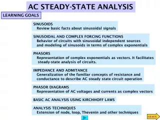
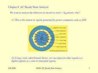
i(t). + v(t) -. p(t) = v(t)i(t). Specifically, if v(t) and i(t) are sinusoids, the power, p(t), will also be a sinusoid:. Using the trig identity:. We can write:. Steady-State AC Power.

E N D
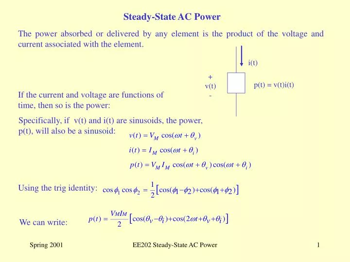
i(t) + v(t) - p(t) = v(t)i(t) Specifically, if v(t) and i(t) are sinusoids, the power, p(t), will also be a sinusoid: Using the trig identity: We can write: Steady-State AC Power The power absorbed or delivered by any element is the product of the voltage and current associated with the element. If the current and voltage are functions of time, then so is the power: EE202 Steady-State AC Power
Example 9.1 p(t) v(t) i(t) EE202 Steady-State AC Power
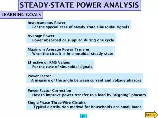
Average Power The average value of any periodic waveform can be found by integrating (summing) the function over one complete period and dividing by the length of the period. The average value of a sinusoid such as a sinusoidal voltage or current, then, is zero: The average value of the instantaneous power function, however, is not zero: EE202 Steady-State AC Power
+ I=I I - + Z=Z Z - + V=V V - Average Power- Continued If Z is purely resistiveZ = 0 and PAVG = VMIM/2 since cos(0) = 1. If Z is purely reactiveZ = 90 and PAVG =0 since cos(90) =0. Reactive elements absorb (store) power during one half cycle and deliver (release) that power during the next half cycle. EE202 Steady-State AC Power
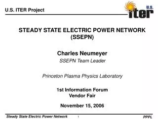
ZTH=ZTT + VTH = VOCV - + VL=VLVL - + - ZL Maximum Average Power Transfer PL , the power delivered to ZL , is maximized whenever ZL = Z*TH (The load impedance is equal to the complex conjugate of the Thevenin equivalent impedance). EE202 Steady-State AC Power
It is easily shown that for a sinusoidal signal: So, the 110Vrms household power is a sinusoid with a peak value of: Effective (RMS) Value The effective (or rms) value of a periodic signal is the dc equivalent value. For example, household power is typically 110V, rms. This means, that a resistive load connected to 110V ac source would absorb the same amount of power if it were connected to a 110V dc source. The term rms stands for root-mean-square and comes from the mathematical definition of effective value: The rms value of non-sinusoidal signals must be found by applying the definition. EE202 Steady-State AC Power
But these can be re-written in terms of rms values: For a resistor: Effective (RMS) Values In Power Calculations The average power formulas were written in terms of the peak values of the sinusoidal voltage and current: EE202 Steady-State AC Power
The Power Factor For a given load, the average ac power absorbed by the load is given by: I=Irmsi P = VrmsIrmscos (v -i) + V=Vrmsv - ZL Notice that the passive sign convention is being used: power absorbed (+) , power generated (-) The product VrmsIrmsis called the apparent power, and is the power that would be delivered if ZL were a purely resistive load. The units for P, sometimes called the real power, is watts (W). However, apparent power is specified in volt-amps (VA) or kilovolt-amps (kVA). The power factor (pf) is the ratio of the real power to the apparent power and is given by: EE202 Steady-State AC Power
I=Irmsi P = VrmsIrmscos (v -i) + V=Vrmsv - ZL The Power Factor - Continued For a purely resistive load, pf =1 since the voltage and current are in phase (v = i ) For a purely reactive load, pf =0 since the voltage and current are 90 out of phase. The pf will range between 0 and 1 since the phase angle between the voltage and current varies between 90 . The power factor angle, (v - I), is determined by the angle of the impedance ZL, since I = V/ZL. If ZL is inductive (ZL = R + jX = Z +), then the pf angle will be negative and I will lagV lagging power factor. If ZL is capacitive (ZL = R - jX = Z-), then the pf angle will be positive and I will leadV leading power factor. EE202 Steady-State AC Power
RW = 0.08 VS P=88kW @ 0.707pf lagging Example 9.12 + 480 V rms - IL An industrial load consumes 88kW at a pf of 0.707 lagging. The voltage at the load is 480V (rms), find the total power supplied by the source if the load is connected to the source via a transmission line that has a total resistance pf 0.08 . P = 88kW = VrmsIrmspf Irms= 88kW/(480V 0.707) Irms= 259.3 A rms. Pwire = (259.3 A)2 0.08 = 5.38kW Psource = 88kW + 5.38kW = 93.38 kW. Suppose that the load power is maintained at 88 kW, but that the pf is improved to 0.9, determine the rms load current and the power delivered by the source. P = 88kW = VrmsIrmspf Irms= 88kW/(480V 0.9) Irms= 203.7 A rms. PWire= (203.7 A)2 0.08 = 3.31kW Psource = 88kW + 3.31kW = 91.31 kW. EE202 Steady-State AC Power
P = real power (Watts) Q = reactive power (volt-amps reactive or VARs) Complex Power Complex power is defined as follows: Complex power has magnitude and phase and is found by multiplying the voltage phasor with the complex conjugate of the current phasor. The expression above represents the complex power in polar form, but we can also represent it is rectangular form. S = P + jQ EE202 Steady-State AC Power
S Q z P It can also be shown that: Complex Power - Continued As stated previously, the complex power is composed of a real part (Watts) and an imaginary part (VARS). S = P + jQ P = Re(S) and Q = Im(S) The magnitude of S, is what we have called the apparent power (VA), and is the hypotenuse of the power triangle. Some observations can be made from the power triangle using trig identities: P = |S|cos z Q = |S|sinz |S| = [P2+Q2]0.5 z = tan-1(Q/P) EE202 Steady-State AC Power
S Q z P P S = P - jQ = |S|-Z (capacitive load) z (Leading pf) -Q S If the load ZL is capacitive, ZL= R - jX, then Z is negative and Q is also negative, as shown above. This is called a leading pf since the current leads the voltage. The Power Triangle S = P + jQ = |S|Z (inductive load) (Lagging pf) If the load ZL is inductive, ZL= R + jX, then Z is positive and Q is also positive, as shown in the diagram above. This is called a lagging pf since the current lags the voltage. If the load ZL is purely resistive, ZL= R, then Z =0 and Q =0. In this case, P = S. EE202 Steady-State AC Power
Power Factor Correction The overall power factor of the typical industrial plant is lagging due to the inductive nature of the devices used: motors and transformers. It is generally economically viable to take some steps to improve (correct) the overall power factor. There are at least two benefits to improving power factor: (1) the same amount of real power can be delivered at a lower current; (2) most power suppliers charge for the VAs used, not for Watts. To improve power factor, a capacitive load is added to the system to offset the inductive VARs generated by other equipment. Often, the only function of the capacitive load is to improve power factor. EE202 Steady-State AC Power
Ic VS Inew Iold Power Factor Correction - continued Inew = Iold + IC • Since the capacitive current leads VS by 90, Inew = Iold + IC will be smaller in magnittde than the original current. • Also, the phase angle between the voltage and current will be closer to zero (power factor will be closer to unity). EE202 Steady-State AC Power
Sold QC Qold old P new Snew Power Factor Correction - continued Power factor improvement can also be visualized using power triangles: Pnew = Pold = P Qnew = Qold - QC Snew = P + jQnew new = tan-1[(Qold - QC)/P] EE202 Steady-State AC Power
induction motor kayak mold Sold = 50k/0.8 Sold = 62.5kVA Snew = 50k/0..95 Snew = 52.6kVA Qold = S sinold Qold = 37.7kVAR Qnew = S sinnew Qnew = 16.4kVAR old P = 50kW new P = 50kW Example 9.15 Plastic kayaks are manufactured using a process called rotomolding, which is illustrated in the diagram below. Molten plastic is injected into a mold, which is then spun the long axis of the kayak until the plastic cools, resulting in a hollow, one-piece craft. Suppose the induction motors used to spin the molds consume 50kW of power at a 0.8 lagging pf. The power source is 2200 , rms. Determine the rating of the capacitive reactance required to raise the pf to 0.95 lagging. Also, calculate the new current demanded from the 220V source. new = cos-1(0.95) = 18.2 Solution: old = cos-1(0.8) = 36.87 Qc = Qnew - Qold = 21.1kVAR Inew = S/V = 52.6kVA/220V = 239A Iold = S/V = 62.5kVA/220V = 284A EE202 Steady-State AC Power