Download
1 / 1
10 likes | 117 Views
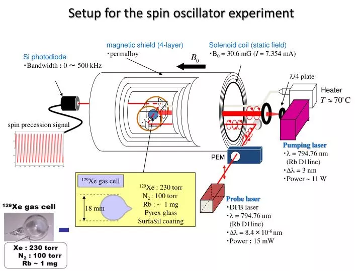
Setup for the spin oscillator experiment. Solenoid coil (static field) ・ B 0 = 30.6 mG ( I = 7.354 mA). magnetic shield (4-layer) ・ permalloy. Si photodiode ・ Bandwidth : 0 ~ 500 kHz. l /4 plate. Heater. spin precession signal. Pumping laser ・ l = 794.76 nm (Rb D1line)

E N D
Setup for the spin oscillator experiment Solenoid coil (static field) ・B0 = 30.6 mG (I = 7.354 mA) magnetic shield (4-layer) ・permalloy Si photodiode ・Bandwidth: 0 ~ 500 kHz l/4 plate Heater spin precession signal Pumping laser ・l = 794.76 nm (Rb D1line) ・Dl = 3 nm ・Power ~ 11 W PEM 129Xe gas cell 129Xe : 230 torr N2 : 100 torr Rb : ~ 1 mg Pyrex glass SurfaSil coating Probe laser ・DFB laser ・l = 794.76 nm (Rb D1line) ・Dl = 8.4×10⁻⁶ nm ・Power : 15 mW 18 mm