Download
1 / 37
400 likes | 539 Views
Chapter 10. Cellular Wireless Networks. Wen-Shyang Hwang KUAS EE. Cellular Network Organization. Use multiple low-power transmitters (100 W or less) Areas divided into cells Each served by its own antenna Served by base station consisting of transmitter, receiver, and control unit

E N D
Chapter 10. Cellular Wireless Networks Wen-Shyang Hwang KUAS EE.
Cellular Network Organization • Use multiple low-power transmitters (100 W or less) • Areas divided into cells • Each served by its own antenna • Served by base station consisting of transmitter, receiver, and control unit • Band of frequencies allocated • Cells set up such that antennas of all neighbors are equidistant (hexagonal pattern)
Frequency Reuse • Adjacent cells assigned different frequencies to avoid interference or crosstalk • Objective is to reuse frequency in nearby cells • 10 to 50 frequencies assigned to each cell • Transmission power controlled to limit power at that frequency escaping to adjacent cells • The issue is to determine how many cells must intervene between two cells using the same frequency
Approaches to Cope with Increasing Capacity • Adding new channels • Frequency borrowing – frequencies are taken from adjacent cells by congested cells • Cell splitting – cells in areas of high usage can be split into smaller cells • Cell sectoring – cells are divided into a number of wedge-shaped sectors, each with their own set of channels • Microcells – antennas move to buildings and lamp posts
Cellular Systems Terms • Base Station (BS) – includes an antenna, a controller, and a number of receivers • Mobile telecommunications switching office (MTSO) – connects calls between mobile units • Two types of channels available between mobile unit and BS • Control channels – used to exchange information having to do with setting up and maintaining calls • Traffic channels – carry voice or data connection between users
Steps in an MTSO Controlled Call between Mobile Users • Mobile unit initialization • Mobile-originated call • Paging • Call accepted • Ongoing call • Handoff
Other Functions in an MTSO Controlled Call • Call blocking – busy tone • Call termination – channel released • Call drop – interference or weak signal • Calls to/from fixed and remote mobile subscriber – connect to PSTN
Mobile Radio Propagation Effects • Signal strength • Must be strong enough between base station and mobile unit to maintain signal quality at the receiver • Must not be so strong as to create too much cochannel interference with channels in another cell using the same frequency band • Fading • Signal propagation effects may disrupt the signal and cause errors • Handoff (in U.S.) or handover (ITU) • Network initiated – network decision • Mobile unit assisted – feedback to network for decision
Handoff Performance Metrics used to decide • Cell blocking probability – probability of a new call being blocked • Call dropping probability – probability that a call is terminated due to a handoff • Call completion probability – probability that an admitted call is not dropped before it terminates • Probability of unsuccessful handoff – probability that a handoff is executed while the reception conditions are inadequate • Handoff blocking probability – probability that a handoff cannot be successfully completed • Handoff probability – probability that a handoff occurs before call termination • Rate of handoff – number of handoffs per unit time • Interruption duration – duration of time during a handoff in which a mobile is not connected to either base station • Handoff delay – distance the mobile moves from the point at which the handoff should occur to the point at which it does occur
Handoff Strategies Used to Determine Instant of Handoff • Relative signal strength • Relative signal strength with threshold • Relative signal strength with hysteresis • Relative signal strength with hysteresis and threshold • Prediction techniques
Power Control • Design issues making it desirable to include dynamic power control in a cellular system • Received power must be sufficiently above the background noise for effective communication • Desirable to minimize power in the transmitted signal from the mobile • Reduce cochannel interference, alleviate health concerns, save battery power • In SS systems using CDMA, it’s desirable to equalize the received power level from all mobile units at the BS
Types of Power Control • Open-loop power control • Depends solely on mobile unit • No feedback from BS • Not as accurate as closed-loop, but can react quicker to fluctuations in signal strength • Closed-loop power control • Adjusts signal strength in reverse channel based on metric of performance • BS makes power adjustment decision and communicates to mobile on control channel
Traffic Engineering • Ideally, available channels would equal number of subscribers active at one time • In practice, not feasible to have capacity handle all possible load • For N simultaneous user capacity and L subscribers • L < N – nonblocking system • L > N – blocking system • Degree of blocking? • Probability that call request is blocked?(What capacity is needed to achieve a certain upper bound on probability of blocking?) • If blocked calls are queued • What is the average delay?(What capacity is needed to achieve a certain average delay?)
Traffic Intensity • Load presented to a system: • = mean rate of calls attempted per unit time • h = mean holding time per successful call • Traffic Intensity A: • average number of calls arriving during average holding period • A measure of busy-hour traffic, as input of a traffic model
Factors that Determine the Nature of Traffic Model • Manner in which blocked calls are handled • Lost calls delayed (LCD) – blocked calls put in a queue awaiting a free channel • Blocked calls rejected and dropped, two assumptions: • Lost calls cleared (LCC) – user waits before another attempt • Lost calls held (LCH) – user repeatedly attempts calling • Number of traffic sources • Whether number of users is assumed to be finite or infinite
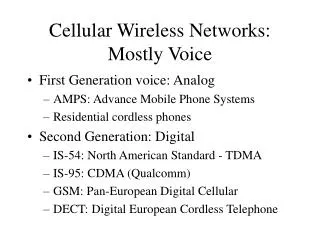
First-Generation Analog • Advanced Mobile Phone Service (AMPS) • In North America, two 25-MHz bands allocated to AMPS • One for transmission from base to mobile unit • One for transmission from mobile unit to base • Each band split in two to encourage competition • Frequency reuse exploited
AMPS Operation • Subscriber initiates call by keying in phone number and presses send key • MTSO verifies number and authorizes user • MTSO issues message to user’s cell phone indicating send and receive traffic channels • MTSO sends ringing signal to called party • Party answers; MTSO establishes circuit and initiates billing information • Either party hangs up; MTSO releases circuit, frees channels, completes billing
Differences Between First and Second Generation Systems • Digital traffic channels – first-generation systems are almost purely analog; second-generation systems are digital • Encryption – all second generation systems provide encryption to prevent eavesdropping • Error detection and correction – second-generation digital traffic allows for detection and correction, giving clear voice reception • Channel access – second-generation systems allow channels to be dynamically shared by a number of users (TDMA or CDMA)
Mobile Wireless TDMA Design Considerations • Number of logical channels (number of time slots in TDMA frame): 8 • Maximum cell radius (R): 35 km • Frequency: region around 900 MHz • Maximum vehicle speed (Vm):250 km/hr • Maximum coding delay: approx. 20 ms • Maximum delay spread (m): 10 s • Bandwidth: Not to exceed 200 kHz (25 kHz per channel)
GSM Network Architecture Global system for mobile communications
Mobile Station • Mobile station communicates across Um interface (air interface) with base station transceiver in same cell as mobile unit • Mobile equipment (ME) – physical terminal, such as a telephone or PCS • ME includes radio transceiver, digital signal processors and subscriber identity module (SIM) • GSM subscriber units are generic until SIM is inserted • SIMs roam, not necessarily the subscriber devices
Base Station Subsystem (BSS) • BSS consists of base station controller and one or more base transceiver stations (BTS) • Each BTS defines a single cell • Includes radio antenna, radio transceiver and a link to a base station controller (BSC) • BSC reserves radio frequencies, manages handoff of mobile unit from one cell to another within BSS, and controls paging
Network Subsystem (NS) • NS provides link between cellular network and public switched telecommunications networks • Controls handoffs between cells in different BSSs • Authenticates users and validates accounts • Enables worldwide roaming of mobile users • Central element of NS is the mobile switching center (MSC)
Mobile Switching Center (MSC) Databases • Home location register (HLR) database – stores information about each subscriber that belongs to it • Visitor location register (VLR) database – maintains information about subscribers currently physically in the region • Authentication center database (AuC) – used for authentication activities, holds encryption keys • Equipment identity register database (EIR) – keeps track of the type of equipment that exists at the mobile station
TDMA Format – Time Slot Fields • Trail bits – allow synchronization of transmissions from mobile units • Encrypted bits – encrypted data • Stealing bit - indicates whether block contains data or is "stolen" • Training sequence – used to adapt parameters of receiver to the current path propagation characteristics • Strongest signal selected in case of multipath propagation • Guard bits – used to avoid overlapping with other bursts
Functions Provided by Protocols • Protocols above the link layer of the GSM signaling protocol architecture provide specific functions: • Radio resource management • Controls setup, maintenance, and termination of channels • Mobility management • Manage the location updating and registration process… • Connection management • Handle setup, maintenance, and termination of calls • Mobile application part (MAP) • Handle most of signaling • BTS management • Perform various management in base station
Advantages of (2G) CDMA Cellular • Frequency diversity – frequency-dependent transmission impairments have less effect on signal • Multipath resistance – chipping codes used for CDMA exhibit low cross correlation and low autocorrelation • Privacy – privacy is inherent since spread spectrum is obtained by use of noise-like signals • Graceful degradation – system only gradually degrades as more users access the system
Drawbacks of CDMA Cellular • Self-jamming – arriving transmissions from multiple users not aligned on chip boundaries unless users are perfectly synchronized • Near-far problem – signals closer to the receiver are received with less attenuation than signals farther away • Soft handoff – requires that the mobile acquires the new cell before it relinquishes the old; this is more complex than hard handoff used in FDMA and TDMA schemes
Mobile Wireless CDMA Design Considerations • RAKE receiver – when multiple versions of a signal arrive more than one chip interval apart, RAKE receiver attempts to recover signals from multiple paths and combine them • This method achieves better performance than simply recovering dominant signal and treating remaining signals as noise • Soft Handoff – mobile station temporarily connected to more than one base station simultaneously
Types of Channels for IS-95 Forward Link • Pilot (channel 0) - allows mobile unit to acquire timing information, provides phase reference and provides means for signal strength comparison • Synchronization (channel 32) - used by mobile station to obtain identification information about cellular system • Paging (channels 1 to 7) - contain messages for one or more mobile stations • Traffic (channels 8 to 31 and 33 to 63) – the forward channel supports 55 traffic channels
Forward Traffic Channel Processing Steps • Speech is encoded at a rate of 8550 bps • Additional bits added for error detection • Data transmitted in 20-ms blocks with forward error correction provided by a convolutional encoder • Data interleaved in blocks to reduce effects of errors • Data bits are scrambled, serving as a privacy mask • Power control information inserted into traffic channel • DS-SS function spreads the 19.2 kbps to a rate of 1.2288 Mbps using one row of 64 x 64 Walsh matrix • Digital bit stream modulated onto the carrier using QPSK modulation scheme
ITU’s View of Third-Generation Capabilities • Voice quality comparable to the public switched telephone network • 144 kbps data rate available to users in high-speed motor vehicles over large areas • 384 kbps available to pedestrians standing or moving slowly over small areas • Support for 2.048 Mbps for office use • Symmetrical / asymmetrical data transmission rates • Support for both packet switched and circuit switched data services • An adaptive interface to the Internet to reflect efficiently the common asymmetry between inbound and outbound traffic • More efficient use of the available spectrum in general • Support for a wide variety of mobile equipment • Flexibility to allow the introduction of new services and technologies
CDMA Design Considerations • Bandwidth – limit channel usage to 5 MHz • Chip rate – depends on desired data rate, need for error control, and bandwidth limitations; 3 Mcps or more is reasonable • Multirate – advantage is that the system can flexibly support multiple simultaneous applications from a given user and can efficiently use available capacity by only providing the capacity required for each service