Download
1 / 22
220 likes | 321 Views
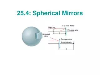
Chapters 25.4 and 26 to 26.3. How current flows. x. 1. 2. 3. EMF—Electromotive Force. Any chemical, solar, mechanical, heat method of creating a potential difference Batteries Alternator, dynamo Solarcell, photovoltaic Thermocouple Symbol E Units: volts. A simple circuit. i.

E N D
How current flows x 1 2 3
EMF—Electromotive Force • Any chemical, solar, mechanical, heat method of creating a potential difference • Batteries • Alternator, dynamo • Solarcell, photovoltaic • Thermocouple • Symbol E • Units: volts
EMF Devices • Ideal EMF device– no internal resistance • Real EMF device– some internal resistance
Batteries • Several Different Types of Batteries (called cells) • Wet Cell (left) • Car Batteries • High Current Apps • Dry Cells (Zn-Cu paste) • Dry Cell Ratings • AAA 20 mA • AA 25 mA • C 80 mA • D 150 mA • Akaline Cells • AAA 200 mA • AA 300 mA • C 500 mA • D 600 mA • EMF=1.5 V • Cells are constant voltage sources: 1.5 3 6 9 12 15 24 48 V e-e- PbO2 Pb PbSO4 PbSO4 PbO2 Pb Pb PbO2 SO4 H2
Internal Resistance • The battery itself can have some resistance to current flow • Could be terminals • Could be plates or paste • Could be combination PbO2 Pb PbO2 Pb Pb PbO2 SO4 H2
Internal Resistance • We treat the internal resistance as if an external resistor had been added to the circuit just ahead of the positive terminal
Terminal Voltage (Effective Voltage) EMF R Vab=Va-Vb=EMF-iR va vb
Dr. Womble Loop Rule • The algebraic sum of changes in potential encountered in a complete traversal of the circuit must be zero. • AKA Kirchoff’s Loop Rule • Consider Nashville Panama City Total Elevation Change = 0
Resistance rule • For a move through a resistor in the direction of current, the change in potential is –iR • If the move opposes the current then the change in potential is +iR. move Va-Vb= +iR Va-Vb= -iR Vb Va i
EMF Rule • For a move from the negative terminal to the positive terminal then the change in potential is +EMF • For a move from “+” to “-” then the change in potential is -EMF move -EMF +EMF
Putting these ideas into practice i.e changing a circuit into an equation X • Pick a direction for the current. • Pick a direction of circuit traversal • 3. Sum the potentials as you traverse the circuit My move R=65 W From X, +iR+EMF=0 EMF=-iR 5=-65i i=-0.076 A or -76 mA EMF=5 V i The negative sign means that we guessed the wrong direction for the current.
Resistors in Series • Connected resistances are said to be in series when a potential difference that is applied across their combination is the sum of the resulting potential differences across all the resistances. R3 E-iR1-iR2-iR3=0 E E Req R2 R1 So Req=R1+R2+R3
Reducing Networks, If You Can, then DO SO! • Always try to reduce the total number of variables by using the equivalent resistance. • For N resistors in series, the equivalent resistance is • Req=R1+R2+….+RN
How to find a potential difference • To find the potential difference between any two points • Start at one point • Traverse the circuit following any path • Add algebraically the changes in potential Point A R3 Blue— Va –iR3-iR2=Vb Va-Vb=i(R3+R2) i E R2 Red— Va-E+iR1=Vb Va-Vb=E-iR1 Point B R1
One last word on internal resistance • Recall Power, P=Vi a X E-ir=0 Va+ir-E=Vb Va-Vb=E-ir P=iV <-(Va-Vb) P=i(E-ir) P=Ei-i2r r i E X b Power of EMF Device Thermal dissipation (losses)
Junction Rule • Sum of all currents entering a junction must equal the sum of all currents leaving the junction. i3 i1 i3 i1 i2 i2 i2 i3 i1 i1+i2+i3=0 i1+i2=i3 i1+i3=i2 IN = OUT
Resistors in Parallel • Connected resistances are said to be in parallel when a potential difference that is applied across their combination results in that same potential difference across each resistance. i1 i2 i3 i E E R1 R2 R3 i=i1+i2+i3 i E Req
Resistor Color Codes • Color Codes Color Value Tolerance Black 0 Brown 1 1% Red 2 2% Orange 3 3% Yellow 4 4% Green 5 Blue 6 Violet 7 Gray 8 White 9 Gold 5% Silver 10% No Color 20% 1 2 3 T Band1*10+Band2 x 10^ Band 3 +/- Band T
Guidelines for Problem Solving • Replace network of resistors with their equivalents (if possible) • If you can’t simplify to a single loop, then use the junction rule and the loop rule to set up a series of equations. Be sure to: • Pick a direction of current (sign is a mathematical convention) • If you traverse a resistor against the current then +iR else –iR • If you traverse an EMF source from low potential to high potential then the EMF is positive, else negative. • You have the following arbitrary choices • Directions of currents • Which loops to use • Direction of traversal of each loop • Starting point and ending point • ABOVE ALL, REMEMBER: • TRAVERSE THE LOOP COMPLETELY • ONCE YOU HAVE CHOSEN A DIRECTION OF THE CURRENT YOU MUST STICK WITH THIS DIRECTION UNTIL YOU HAVE FINISHED THE PROBLEM.