Download
1 / 37
390 likes | 572 Views
Structural Response to Tsunami Loading The Rationale for Vertical Evacuation. Laura Kong IOC ITIC Ian Robertson University of Hawaii at Manoa Harry Yeh Oregon State University. Topics. Pilot Study on current code tsunami design Lessons from Indian Ocean Tsunami FEMA ATC-64 Project

E N D
Structural Response to Tsunami LoadingThe Rationale for Vertical Evacuation Laura Kong IOC ITIC Ian Robertson University of Hawaii at Manoa Harry Yeh Oregon State University
Topics • Pilot Study on current code tsunami design • Lessons from Indian Ocean Tsunami • FEMA ATC-64 Project • NEESR-SG Proposal - Performance Based Tsunami Engineering, PBTE
Seismic/Tsunami Construction,Phase I: A Pilot Study • Initiated and funded by Washington State Emergency Management Division • One year pilot study • Joint effort by OSU and UH Manoa • Culminating in development of proposal for future design guideline development
Project Scope • Review current codes for tsunami loading provisions • Evaluate prototype structures for seismic/tsunami design • Review past tsunami damage
1. Review Current Codes • City and County of Honolulu Building Code (CCH) • FEMA Coastal Construction Manual (FEMA CCM) • Dames and Moore 1980 • 1997 Uniform Building Code (UBC 97) • 2000 and 2003 International Building Code (IBC) • ASCE 7-98 and ASCE 7-02 (ASCE 7) Provisions of codes: • Predominantly intended for residential construction or small scale structures. • Code provisions developed for storm wave conditions, storm surge and river flooding. • CCH and FEMA CCM add reference to tsunami conditions.
Tsunamis covered in CCH and FEMA CCM FEMA CCM states that : “Tsunami loads on residential buildings may be calculated in the same fashion as other flood loads; when the tsunami forms a borelike wave, the flood velocities are substantially higher. Conclusion of FEMA CCM: Tsunami loads are too great and not feasible or practical to design normal structures to withstand these loads. (Note that this report was intended for use in low-rise residential construction)
Tsunami Design Vs. Design Stillwater Depth FEMA CCM: Section 11.7 Figure 11-16
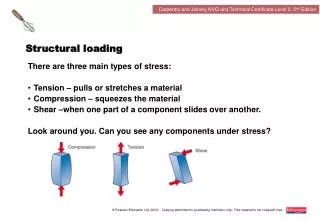
Design Considerations • Hydraulic Lateral Forces • full structure • individual elements • Impact Force • floating debris • Buoyancy Force • Scour
Design Considerations • Hydraulic Lateral Forces • Hydrostatic • Surge Force • Breaking Wave Force • Hydrodynamic • Impact Force
Design Considerations • Hydraulic Lateral Forces • Hydrostatic • Surge Force • Breaking Wave Force • Hydrodynamic • Impact Force
Design Considerations • Hydraulic Lateral Forces • Hydrostatic • Surge Force • Breaking Wave Force • Hydrodynamic • Impact Force
Design Considerations • Hydraulic Lateral Forces • Hydrostatic • Surge Force • Breaking Wave Force • Hydrodynamic • Impact Force
Design Considerations • Hydraulic Lateral Forces • Hydrostatic • Surge Force • Breaking Wave Force • Hydrodynamic • Impact Force
Design Considerations • Hydraulic Lateral Forces • Hydrostatic • Surge Force • Breaking Wave Force • Hydrodynamic • Impact Force
Values: Wood 1.0 sec Steel 0.5 sec RC 0.1 sec • Impact Force (CCH) at where W = 1000 lbs Example: Wood Steel RC
Loading Combinations • If walls not designed to break away: • Hydrostatic force on building elevation, plus hydrodynamic force on sides of structure, plus impact force. • Breaking wave force on building elevation, plus hydrodynamic force on sides of structure, plus impact force. • Surge force on building elevation, plus hydrodynamic force on sides of structure, plus impact force. • Codes call for break-away walls: In-fill wall capacity: min. 10 psf and max. 20 psf
2. Prototype Buildings Seismic and Wind Design of Concrete Buildings. S.K. Ghosh and David A. Fanella 2003. • Includes examples of typical concrete building design for Gravity, Wind and Seismic loading. • Considers various wind exposure conditions and seismic design categories. • Shows sample column, beam and shear wall design.
Tsunami Design Criteria 3 Meter Flow Depth 5 Meter Flow Depth 10 Meter Flow Depth Building Design Criteria Seismic and Wind Design Criteria SDC – Seismic Design Category (Seismic Hazard and Soil Type)
Building 1 Results Base Shear • Non-break-away walls
Building 1 Results Base Shear • Break-away walls
Building 1Forces on Structural Members Column C4 Shear Wall
Building 1 Results • Column – Design Forces Code Tsunami Forces compared with Seismic Design
Building 1 Results • Column - Actual Strength Code Tsunami Forces vs As-Built Strength
Building 1 Results • Shear Wall - Actual Strength Code Tsunami Forces vs As-Built Strength
Building 1 Results • Shear Wall - Actual Strength Recommended Tsunami Forces vs As-Built Strength
Conclusions • The USA building codes do not adequately address the flow velocity and subsequent structural loading during a tsunami. Experimental validation of the velocity, flow depth and loading expressions is needed. • The tsunami forces often exceed the design forces based on wind and seismic conditions • However, a review of three typical prototype buildings indicated that the as-built capacity of individual members is often adequate for the tsunami loads • The prototype building with moment-resisting frame or dual system was able to resist the tsunami forces
Conclusions (cont.) • The prototype building with shear wall-frame system was able to resist the tsunami forces, however individual shear walls perpendicular to the tsunami flow may fail and lead to progressive collapse of the building • The prototype building with bearing wall system was not able to resist the tsunami loads and is not recommended for construction in tsunami inundation zones • A structure must resist both the initial earthquake ground shaking, as well as the subsequent tsunami loads, so that vertical evacuation can be recommended to levels above the expected maximum flow
Recommendations • Analytical Modeling and experimental verification of tsunami flow depth and velocity should be performed using a large-scale wave tank • Hydrodynamic force and impact force are the most probable during a tsunami. • Wave tank studies should also be performed to verify hydrodynamic loading due to tsunami flow, and impact due to waterborne debris • Based on these studies the code tsunami loading equations should be revised.
Recommendations (cont) • All non-structural walls at the lower levels should be designed to break-away during a tsunami event • Open moment frame or dual systems are recommended for lateral framing of buildings in tsunami inundation areas • Buildings in tsunami inundation areas should avoid the use of bearing walls or large structural walls perpendicular to the anticipated tsunami flow • Structures must be able to resist the local source earthquake, which often precedes the tsunami, with limited structural damage
Final Recommendation • Vertical evacuation in multi-story reinforced concrete (and structural steel) buildings is an appropriate policy for: • All near-source tsunamis • Remote-source tsunamis in densely populated areas where horizontal evacuation is not feasible
FEMA ATC-64 project • Initiated by FEMA as follow-on to Pilot Study • $400,000 funding for 2-year effort • “Development of Design and Construction Guidance for Special Facilities for Vertical Evacuation from Tsunami” • Applied Technology Council Project Team • Chris Rojahn – Project Executive Director • Steven Baldridge – Project Technical Director
NEESR-SGPerformance Based Tsunami Engineering, PBTE • Proposal to the NSF George E. Brown Network for Earthquake Engineering Simulation, NEES • Small Group project, $1,600,000 over 4-years • UH, Princeton, Oregon State University • “Development of Performance Based Tsunami Engineering” • Will include numerous tsunami wave basin experiments to validate run-up and 3-D RANS modeling, develop improved loading time-history, scour modeling and structural response. • Result in code adoptable tsunami design provisions