Download
1 / 26
260 likes | 284 Views
Potential difference & resistance. Learning outcomes. • describe the difference between direct and alternating currents • apply the law of conservation of energy to simple circuits

E N D
Learning outcomes • describe the difference between direct and alternating currents • apply the law of conservation of energy to simple circuits • use concepts of electric potential energy, electromotive force and potential difference to describe DC circuits • predict the behaviour of resistors in series and parallel and be able to calculate effective resistances • recognise and use variable resistors, LDRs, LEDs, thermistors • use the relationship between power, potential difference and current to analyse simple circuits • explain how fuses protect electrical appliances & calculate fuse values • critically use a variety of models to show how energy is transferred in simple circuits • develop confidence with electrical equipment: use ammeters, voltmeters and multimeters in simple circuits
Teaching challenges Once students grasp the idea of an electric current, they find it difficult to accept the need for another measure of electricity (voltage, potential difference). It doesn’t help that voltmeters and ammeters look so similar.
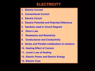
Charge and current Charge is a fundamental property (of protons and electrons). Charge is conserved. Current is the rate of flow of charge past a point. I = current in A,Q = charge in C, t = time in s Current in a wire (SPT simulations) electron drift conventional current
AC and DC Direct current – always in one direction, though flow rate may change e.g. a pulsed current. Alternating current – flow direction changes with time. Flow rate may also change.
Circuits: the energy story KS2:A battery gives electrical ‘push’ to electrons in a circuit. KS3/4:A battery gives electrical ‘push and pull’ to electrons in a circuit. Better: A battery is a chemical store of energy. When connected in a circuit, it transfers energy to a circuit component by doing work on charges located there e.g. in a filament. Law of conservation of energy: energy supplied = work done in the external circuit (some always dissipated as heating).
Lamp brightness comparison Lamps in series, same current. Brightness indicates power.
Other models for circuits In pairs, do the C21 Activity Models of electric circuits. Supplementary powerpoint: teaching models found in school textbooks, collected by Robin Millar, University of York.
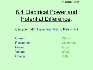
EMF and potential difference A-level: A battery maintains an electric field through the circuit. This enables it to do work on charges wherever there is a potential difference e.g. in a filament. Electromotive force is the energy supplied per unit charge. (work done on each coulomb of charge) Potential difference (p.d.) is the energy transferred per unit charge between two points in a circuit . (work done by each coulomb of charge) Unit (for both) is the volt = joule/coulomb; 1 V = 1 J/C
Sources of EMF chemical cell dynamo mains (dynamo at a power station) photovoltaic cell (solar cell) piezoelectric crystal (gaslighter) EMFs can be added in series in parallel
Resistance When the same p.d. is applied across different conductors, different currents flow. Resistance R of a conductor is defined as the ratio of the potential difference V applied across it to the current I flowing through it. unit: ohm
Current, voltage and resistance Current in a simple circuit will be larger if • voltage of the supply is larger • resistance in the circuit is smaller where R is resistance, is resistivity of the material, l is its length and A is its cross-sectional area. The same relationships apply in networks of identical resistors.
Resistor networks Resistors in series V = V1+ V2 [conservation of energy] IR =IR1 +IR2 R =R1 +R2 R is always larger than any of R1, R2etc Resistors in parallel I = I1 + I2 [conservation of charge] V/R =V/R1 +V/R2 1/R =1/R1 +1/R2 R is always smaller thanany of R1, R2etc
Combining resistors A practical exercise, in pairs. Multimeter: set on resistance range. Black lead from COM terminal Red lead from terminal Use breadboardto configure resistors temporarily. NOTE: Each column of 5 holes is connected together.
Ohmic & non-ohmic conductors • An ohmic conductor has a straight-line graph that passes through the origin (I proportional to V) • Resistance is always the ratio of V to I, not the gradient of the I - V graph. Ohm (1826): replaced voltaic pile with thermocouple as his source of EMF. ‘At constant temperature, the p.d. across a conductor is proportional to the current through it.’
Electrical power and fuses Heating effect of current (Joule, 1841, coil of wire in a jar of water) P = IV =I2R Fuse action: e.g. If live wire contacts the metal body of a kettle, the body is connected to earth, so this produces a current surge and fuse (wire) melts, isolating the appliance from live wire (supply). Fuse value: Use appliance power and mains voltage to calculate its normal current. I = P/V Select next higher fuse rating. Electrical fire hazard when current is too large.
Component characteristics The electrical behaviour of a component is described by its I-V graph. For example: I/V characteristic of a carbon resistor I/V characteristic of a filament lamp I/V characteristic of a semiconductor diode
Practical session • Component characteristics. Collect data and draw the I/ V graph for resistor, lamp and diode. • Investigate how the resistance of LDR and thermistor vary. • Experiments with SEP Energymeter • Getting to know the joule and the watt • Using an energymeter to measure efficiency of energy transfer • Using an energymeter to measure power in electrical circuits
Potential dividers Useful for constructing sensors In pairs,sketch • a dark sensor • a heat sensor • a cold sensor
Electrical energy Power is the rate of energy transfer P = E/ t so E = Pt = IVt units of electrical energy: kW-hrorjoules Paying for electricity: cost per metered kW-hr
Problem-solving Do any (all) of • McDermott Physics by Inquiry Exercises • Physics for You questions on Circuits • TAP 109-3: Lamp and resistor in series • Breithaupt questions from sections13.3 Potential difference, 13.4 Resistance Standard procedure for quantitative problems: Sketch the circuit, write down known quantities, start with an equation in symbols, show all working, include units with the answer.
ICT investigating circuits For example, PhET Circuit Construction Kit (DC only)
In practice Real power supplies cannot maintain their terminal p.d. when they provide larger currents. Explaining why this happens requires another idea.
Support, references www.talkphysics.org SPT 11-14 Electricity & Magnetism Ep4 Getting to grips with voltage Ep5Electrical power: a final look David Sang (ed, 2011) Teaching secondary physics ASE / Hodder PhET simulationsElectricity, Magnets & Circuits Practical Physics Guidance pages e.g.Models of electric circuits