Download
1 / 26
270 likes | 502 Views
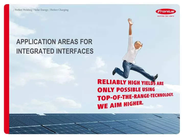
APPLICATION AREAS FOR INTEGRATED INTERFACES. DATA COMMUNICATION APPLICATIONS. FRONIUS SYMO Maximum flexibility for the applications of tomorrow. . FRONIUS GALVO The future-proof inverter for small self-consumption systems.

E N D
DATA COMMUNICATION APPLICATIONS • FRONIUS SYMOMaximum flexibility for the applications of tomorrow. • FRONIUS GALVOThe future-proof inverter for small self-consumption systems.
The Fronius Galvo and Fronius Symo inverters have numerous permanently integrated interfaces that can be used for a variety of practical applications. • The following slides provide an overview of the various application possibilities • How is the inverter connected to the internet? • How can data be saved locally? • How can the inverter be updated? • How can loads be controlled? • How can the inverter send signals? • How can the inverter be controlled remotely? • How is a dynamic power reduction realized? • How can devices from third-party suppliers be integrated? • How are multiple inverters connected?
OVERVIEW OF INTEGRATED INTERFACES EXTERNal INPUT (F.E. fOr A S0-METer) FRONIUS Solar.Net IN FRONIUS Solar.Net OUT USB INTERFACE FLOATING RELAY OUTPUT Digital INPUTS AND OUTPUTS (I/Os) (ONE OF THEM IS A DIGITAL OUTPUT FOR energYmanAgement) Ethernet WLAN AntennA 4 4 6 2 6 1 5 2 3 7 7 1 5 3 8 8
HOW IS THE INVERTER CONNECTED TO THE INTERNET? • The inverter can be connected directly to the router via LAN (Ethernet) or WLAN • When using WLAN, a cable connecting the inverter to the router is not required • Using the internet connection gives the user access to the free Fronius Solar.web online portal as well as Fronius Solar.TV and the Fronius Solar.web App • The connection to Fronius Solar.web ensures that rapid technical support can be provided in the event that servicing is required • Register for Fronius Solar.web at: www.solarweb.com
WLAN/LAN FRONIUS SOLAR.WEB FRONIUS SOLAR.TVFRONIUS SOLAR.WEB APP FRONIUS INVERTER ROUTER PV GENERATOR
HOW CAN DATA BE SAVED LOCALLY? • Data can be saved locally using a USB stick • Simply insert a conventional USB stick and the data from the inverter will be stored on the stick • The data is saved in a CSV file so that it can easily be processed in Microsoft Excel, for example
NOTE: SETTINGS ON THE DISPLAY ACCORDING TO OPERATING INSTRUCTIONS
HOW CAN THE INVERTER BE UPDATED? • Software updates ensure that the latest version of the software is installed on the inverter • The software can be updated using a conventional USB stick; the inverter has an integrated USB interface for this purpose • Save the new software onto the stick, insert it into the inverter and perform the update • No additional hardware is required for the update process
Download the latest software from: www.fronius.com– Solar Electronics – Info & Support –Software Downloads Maximum size of the USB stick: 65 x 30 mm NOTE: SETTINGS ON THE DISPLAY ACCORDING TO OPERATING INSTRUCTIONS
HOW CAN LOADS BE CONTROLLED? • The inverters can turn consumers on and off automatically using power thresholds • If the output level of the photovoltaic system exceeds the preset ON value, the consumer will be switched on • If the output level of the photovoltaic system falls below the preset OFF value, the consumer will be switched off again • Consumers can be connected to the Fronius Galvo and Fronius Symo inverters in two different ways: • using a digital output • using a floating relay contact
The inverters can turn consumers on and off automatically using power thresholds • Variant 1 – using a digital output:Heater example: ON at 2 kW, OFF at 1.5 kW, minimum running time: 60 mins NOTE: SETTINGS ON THE WEB INTERFACE OF THE INTEGRATED WEB SERVER L I/0 1 GND Contactor N
HOW CAN LOADS BE CONTROLLED? • The inverters can turn consumers on and off automatically using power thresholds • Variant 2 – floating relay contact: • Direct switch on from max. 30V and 1A DC – or max. 250V and 4A AC • Swimming pool pump example: ON at 1 kW, OFF at 0.5 kW NOTE: SETTINGS ON THE DISPLAY ACCORDING TO OPERATING INSTRUCTIONS Pin 3 (NO contact) Pin 2 (root) Supply, e.g. 230V AC N
HOW CAN THE INVERTER SEND SIGNALS? • Audiovisual alarm devices can be connected to the relay contact • When an error occurs, the inverter switches the relay contact and the signal starts • The relay contact can be used either as an alarm device or to connect a load NOTE: SETTINGS ON THE DISPLAY ACCORDING TO OPERATING INSTRUCTIONS Pin 2 (root) Pin 3 (NO contact) Supply, e.g. 230V AC N
HOW CAN THE INVERTER BE CONTROLLED REMOTELY? • The ripple control receiver can be connected directly to the inverter so that the PSC can control it remotely • Power reduction and power factor can be controlled using the digital inputs for the ripple control receiver • Digital inputs can be configured by the user
NOTE: SETTINGS ON THE WEB INTERFACE OF THE INTEGRATED WEB SERVER Up to eight inputs can be configured, one output is available for feedback to the PSC.
HOW IS A DYNAMIC POWER REDUCTION REALIZED? • A S0-meter can be connected directly to the inverter, in order to take self-consumption into account for feed-in limits (f.e. 70 % of the kWp, max. 5 kW or similar) • The meter can connected at the feed-in point or directly in the consumption path • The feed-in limit and the number of impulses can be set individually NOTE: MORE DETAILED INFORMATION ON THE INSTALLATION AND SETUP CAN BE FOUND IN THE MANUAL OF THE FRONIUS DATAMANAGER
NOTE: SETTINGS ON THE WEB INTERFACE OF THE INTEGRATED WEB SERVER S0-meter
HOW CAN DEVICES FROM THIRD-PARTY SUPPLIERS BE INTEGRATED? • The open interfaces permit easy communication between the inverters and third-party components • Integrating the photovoltaic system into higher-level energy management or home automation systems is therefore a simple matter • The Fronius Galvo and Symo offer the following open interfaces via Ethernet or WLAN: • JSON • Modbus TCP • For example: Integration into home control system with the LoxoneMiniserver to effectively maximise self-consumption
WLAN Network cable or WLAN Router or switch Parallel operation of Fronius Solar.web and integration into home control system possible.
HOW ARE MULTIPLE INVERTERS CONNECTED? • Multiple Fronius inverters can be connected to each other via the Fronius Solar Net ring, a bus system configured as a ring. • The data connection for Fronius Solar.Net nodes uses a 1:1 connection with 8-pin data cables and RJ45 plugs. A termination plug is plugged in at each end of the ring. • The Fronius Galvo and Fronius Symo inverters are equipped with the required interfaces (Fronius Solar.Net IN and Fronius Solar.Net OUT). • In a Fronius Solar Net ring, only one Fronius inverter with an integrated datalogger is required; the remaining inverters must be "light" variants. NOTE: MORE DETAILED INFO ON CABLING CAN BE FOUNDONLINE IN THE GUIDELINES ONDATCOM CABLING.
Cabling using the Fronius Solar.Net ring: 1) 1) Fronius Solar.Net IN Fronius Solar.Net OUT Fronius Solar.Net OUT Fronius Solar.Net IN Termination plug Termination plug 1) "light" variant
THE SEEDS OF OUR INNOVATIONS 14 Fronius Solar Electronics Division subsidiaries
CONTACT DETAILS • The latest information about our innovations and seminar dates can be found on our homepage: • www.fronius.com