Download
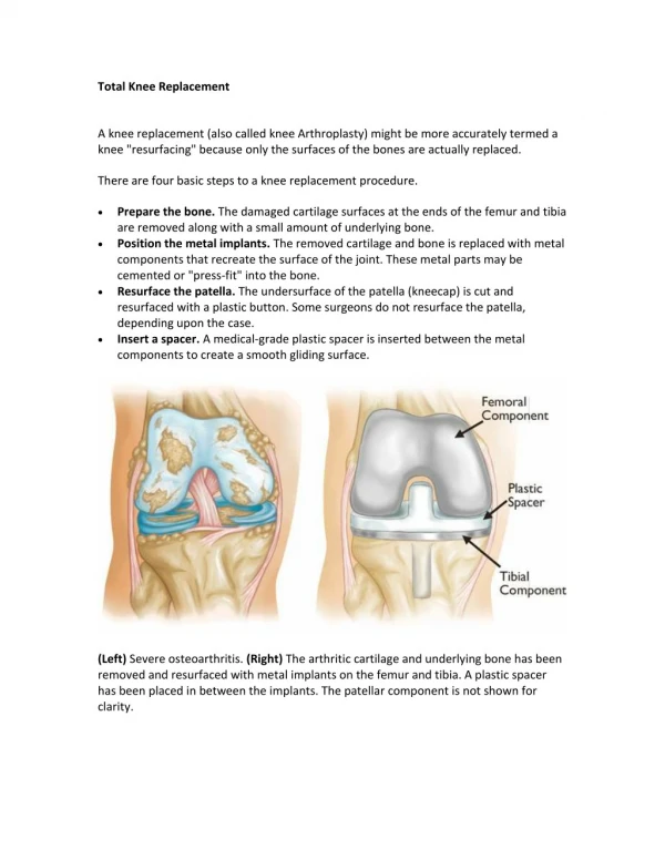
1 / 55
920 likes | 1.64k Views
MRI KNEE ORTHOPEDIC APPROACH. PROF. Dr . : Ahmed M. El- Saeed MD Ain Shams University. MRI knee. Uses non ionizing radiation created by placing patients in strong magnetic field (30.000 times stronger than earth`s m.f.) Has no demonstrated adverse biological effects

E N D
MRI KNEE ORTHOPEDIC APPROACH PROF. Dr. : Ahmed M. El-Saeed MD Ain Shams University
MRI knee • Uses non ionizing radiation • created by placing patients in strong magneticfield(30.000 times stronger than earth`s m.f.) • Has no demonstrated adverse biological effects • Depends on Hydrogen atom (single proton) • When hydrogen proton is placed in magnetic field it align its own m.f. to the direction of external m.f. = steadystate
In this steady state radiofrequency(RF) pulse is applied ----- excites the magnetized proton in the field ----- proton change its alignment with MF • When RF pulse is turned off ---- tendency of the proton to giveupthis energy to restore its alignment in MF before RFP • As proton do so emits RF signals of its own-- through a receiver coil or antenna these signals used to generate images
The rate at which proton returns to their equilibrium positions is regulated by two constants : T1= spin-lattic relaxation time T2= spin-spin relaxation time • T1=results from interaction of the hydrogen nucleus with its molecular environment • T2 =reflects local MF strength surrounding each individual proton • T1&T2 are property of tissue and will vary for different tissues
T1 images have the advantage of being obtainable in relatively short periods while providing good anatomic details • T2 images are excellent for lesion detection because almost all pathologic processes prolong T2 • By varying timing of application of RF pulses (TR=repetition time) and timing of acquisition of the returning signals (TE=echo time) an imaging sequence can accentuate T1 (short TR & TE) or T2 (long TR&TE)
Fat and bone marrow give bright signals (abundant in H2) • Cortical bone, ligaments, tendon and air appearblack(littleH2) • Cartilage, spinal canal and muscles are in the grayscale(intermediate H2) • Fat suppression technique for intense fat signals
Parametersused for MRI knee : FOV=12-16cm Slicethickness =3-4mm planes=Sagittalfor menisci and cruciates =Coronal for collateral ligaments =Axial for patellofemoral joint • Contraindications: absolute= IC aneurysm clips, internal ear devices, pacemakers, defibrillators and metallic eye. Relative= Cardiac valves, Middle ear devices and Penile prostheses
Anatomy of the knee • The coil surrounds knee while imaging
menisci • Different cuts of different sites of the meniscus B C A A B C
Meniscal Anatomy SAGITTAL VIEW
Lateral meniscus • Sagittal plane • lateralmeniscus =bow tie appearance
DISCOID L. MENISCUS 1 2 3
Arrangement of ligaments PCL MM LM ACL
Coronal anatomy • MCL • First meniscus to be seen is MM • Iliotibial band
Posterior Coronal section • Most posterior of the coronal plane the PCL • Lateral=biceps , LCL • Note MM still seen (larger) than LM
Intercondylar notch • Change of femoral shape • Indistinct posterior border is seen • Sharp roof of notch is seen
Grading of meniscal signal= G1 • G1= signal changes not extended to surface • (cut sec—gray)
Grading of meniscal signal=G2 • G2= linear signals common with capsular margin • cut--linear discoloration due to inter substance deg. Cut section
Grading of meniscal signal= G3 • G3= signals extend to articular surface • cut--M tears through surface
Menisci Meniscaltears ch.ch. • abnormalsignal within a meniscus extending to an articular surface 2) alteration in shape and position of meniscus G3
Torn Medial Meniscus1) Abnormal signal • MM tear extending to under surface of mm
Bucket handle tear small post. Segment displaced M. in notch
ACL TEAR 1-ill-defined mass 2-Loss of continuity 3-retraction of torn ends 4-signals within ligament
Secondary signs ACL tear • Bone fragment • Tibial shift forward on femur
Chronic ACL tear ACL attaches to PCL Horizontal ACL
PCL TEAR Retracted ends