Download
1 / 23
230 likes | 238 Views
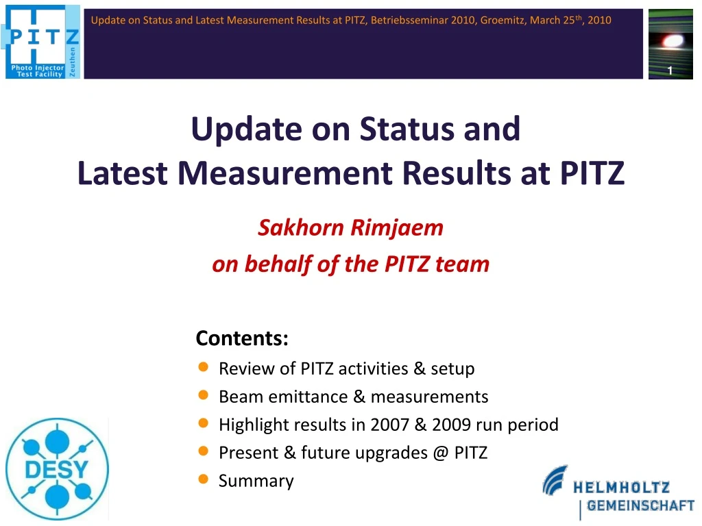
Update on Status and Latest Measurement Results at PITZ. Sakhorn Rimjaem on behalf of the PITZ team. Contents: Review of PITZ activities & setup Beam emittance & measurements Highlight results in 2007 & 2009 run period Present & future upgrades @ PITZ Summary.

E N D
Update on Status and Latest Measurement Results at PITZ Sakhorn Rimjaem on behalf of the PITZ team Contents: • Review of PITZ activities & setup • Beam emittance & measurements • Highlight results in 2007 & 2009 run period • Present & future upgrades @ PITZ • Summary
Photo Injector Test facility at DESY, location Zeuthen (PITZ) Research activities @ PITZ: • Development and optimization of electron source for FLASH & the European XFEL • to produce short electron bunches with small energy spread & smalltransverse emittance (1 um @ 1 nC) • to be capable with long pulse train operation • Preparation (conditioning) & characterization of RF guns for FLASH • Theoretical study of photo injectors by compare experimental results with simulations • R&D on photo injectors in parallel to FLASH operation
PITZ setup: Upgrades ofPITZ1.6(2006-2007) PITZ1.7(2008-2009) new cooling for the gun 5 EMSYs were shifted 60 cm (EMSY1 @ 5.7 m) booster was shifted 60 cm 4 1 gun 4.2 + solenoids (new laser) 6 HEDA1 3 LEDA DDC low energy section (~6.5 MeV) high energy section (~14 MeV) 2
RF gun: L-band (1.3 GHz) nc (copper) standing wave 1.6-cell cavity Bucking solenoid Coaxial RF coupler Photo cathode (Cs2Te) QE~0.5-5% Cathode laser 257 nm 20ps (FWHM) Mirror in vacuum Main solenoid, Bz_peak~0.2T Electron bunch 1nC, ~6.5 MeV RF gun @ PITZ Main properties of PITZ gun: 1-1/2 cell L-band RF cavity with the coaxial RF coupler surrounded with solenoids for beam focusing Cs2Te cathode @ half-cell wall e- production & acceleration → photoemission process → electrons are accelerated by high gradient RF field Typical output electron beams: 1 nC/ bunch ~20 ps bunch length peak current ~50 A up to 800 micro bunches / train max. energy ~ 6.5 MeV
RF gun conditioning: high average power & low dark current • PITZ gun must produce electron beam for the SC linac long pulse trains is required (high average power & good stability) • Gun 4.2: dry-ice sublimation-impulse cleaning significant DC reduction by factor of 10 (previous guns: high-pressure water rinsing) (DC comes mainly from cathode not gun cavity) Gun 3.2 ~60 MV/m Gun 3.1 ~43 MV/m Vertical cleaning setup with 110o rotating nozzle. Gun 4.2 ~60 MV/m • Gun 4.2 demonstrated the 50 kW average. RF power operation • 7 MW peak power, 700 us, 10 Hz repetition rate • Dark current ~280 uA • Gun 4.2 is currently commissioning @ FLASH
New photocathode laser system (developed by MBI) • Ytterbium-doped YAG laser (Yb:YAG ) IR input pulses • UV output pulses • = 257 nm • repetition rate = 1 MHz • up to 800 micro pulses/train • micro pulse energy: 10 J • Optical Sampling System (OSS) • to observe long. Laser pulse train Time structure for FLASH and European XFEL demonstration @ PITZ
FWHM ~ 24 ps FWHM ~ 19 ps Laser pulse shaper flexibility The new laser system can generate a broad variety of longitudinal pulse shapes use 13 individual crystal to determine the shape at different longitudinal positions • Flat-top pulses of different duration and rise/fall time (max. flat-top ~25 ps FWHM) • Gaussian pulses of different duration (FWHM = 2 -14 ps) FWHM ~ 2 ps FWHM ~ 11 ps FWHM ~7 ps
Goal for PITZ gun optimization: small emittance production • Definition: emittance describes the phase space area occupied by the beam • RMS emittance is calculated from • Emittance is a measure for the beam quality Beam quality: brightness (B) can be improved e.g. bunch compressor injector’s property (must be small from the source)
length of the undulator peak power absolute numbers Why emittance must be small? European XFEL FLASH peak current: 5 kA energy spread: 2.5 MeV en = 1 um en = 1um output peak power of the XFEL SASE2@ 0.1 nm (GW) output peak power of FLASH @ 6.4 nm (GW) en = 2 um en = 2 um en = 4 um en = 3 um Q = 1 nC path length in the undulator (m) path length in the undulator (m) • Goal parameters for XFEL can only be reached with high quality electron beam at • the undulator entrance ! • XFEL emittance goal: 1.4 um @ undulator 0.9 um @ injector goal ofPITZ gun
How to measure emittance @ PITZ ? Emittance Measurement System (EMSY) • Single slit scantechnique →combines slit scan & beam size measurement @ screen station slit-mask 10 µm opening Procedure & analysis in2007 run period • took 11 beamlets over the full beam with statistics • (~30 min. for 1 scan) • used 12 bit camera for beamlet measurements • used sheared emittance definition • (used uncorrelated local divergence, X’rms→ over estimate emit.) L
2007 highlight results: 1st demonstration of beam emittance for European XFEL for ~60 MV/m we obtained • Gun 3.2 (high DC) with laser wavelength of 262 nm, 20 ps (FWHM), 6-7 ps rise/fall times • Gun gradient ~60 MV/m • Gun & booster phase were on-crest • Momentum from gun & booster: 6.4 & 14.5 MeV/c @ 1nC for 100 % RMS emittance ! S-shaped x-x´ phase space 10 % charge cut in the tails of the phase space distribution (remove non-lasing electrons) normalized projected emittance = ~0.9 um first demonstration of the beam quality required for the European XFEL !!!
2009 results: Emittance measurement procedure & analysis improvements • Accelerate slit scan time by taking beamlet images during continuous slit movement • measurement time improvement (exclude analysis time): ~20sec. vs. ~30 min (2007) • Define more accurate criteria for beamlet image quality (use full dynamics range of 12 bit camera) • Take statistics of several slit scans (to include uncertainty of machine & measurements) • 2D scaled emittance scaled factor to correct for low sensitivity losses from beamlet measurement conservative emittance estimation (factor bigger than 1 !!!!!) • Check on saturation after the scan • data are taken • Take statistics over all pixel in all • beamlets e.g. too low intensity e.g. may be saturation counts counts pixel intensity pixel intensity beam size @ slit position beamlet@ observation screen
2009 results: Nominal 1 nC measurements (21.08.2009M) preliminary results 3.0 2.5 y=1.26 um ey=1.26 mm mrad 2.0 mm mrad 1.5 1.0 Xemit Yemit 0.5 x=0.76 um ex=0.76 mm mrad XYemit 0.0 378 380 382 384 386 388 390 392 394 Imain, A • Gun 4.2 with low dark current • Emit. measurement location @ 5.7 m from cathode • (slit-to-beamlet screen distance: 2.64 m) • Q = 1 nC • Gun phase: +6o off-crest • Booster phase: on-crest • Laser temporal profile: 2.1/23.1/2.4 ps • Laser spot size = 0.36 mm min. exy = 0.98 um 100% RMS emittance (no charge cut in data analysis)
1.6 1.6 1.4 1.4 1.2 1.2 EmitY emittance, mm mrad EmitX 1.0 1.0 EmitXY beam size, mm Xrms 0.8 0.8 Yrms XYrms 0.6 0.6 0.4 0.4 0 2 4 6 8 10 12 14 Measurement 2009 results: Statistic measurements for nominal 1 nC Beam size and emittance measurements for 1 nC 22.8.09 21.8.09 best emittance on 22.08.2009M Short term (~3 hours): ~4-7% (stdev) Long term(~4 days): ~6-8.5% (stdev) ~16-21% (peak-to-peak) RF gun phase instability emittance value fluctuation
1 nC Study of emittance vs.BSA size and charge 0.5 nC gun of +6 deg off-crest, booster on-crest 0.25 nC 1.8 0.1 nC 1.6 1.4 1.2 Emit-XY (um) 1.0 0.8 0.6 0.4 0.2 0.0 0.1 0.2 0.3 0.4 0.5 Laser spot size (mm) 0.0 0.2 0.4 0.6 0.8 1.0 1.2 1.4 1.6 1.8 2.0 BSA size (mm) 2009 results: Emittance vs. bunch charge (gun 4.2)
2009 results: Emittance vs. bunch charge (with charge cut) 10% cut ~0.7-0.8 mm-mrad (remove non-lasing electrons) → beyond XFEL requirement 5% cut ~0.4 um (comparable to LCLS result)
Upgrades of PITZ beamline in shutdown 2009-2010 gun 4.2 HH gun 4.1 CDS booster tomography module • Upgrades in (2009/2010): • Exchange of gun 4.2 to 4.1 (gun 4.2 gun for FLASH) • Exchange of booster cavity • Installation of new phase space tomography module
“10”-MW klystron T-combiner forward1 reflected1 reflected2 forward2 gun (E0,f) Gun 4.1 in PITZ beamline • Gun 4.1 installed in PITZ tunnel (January 2010) • the same design and production as the gun 4.2 • dry-ice cleaning technique was applied • under conditioning process 10MW in-vacuum directional coupler has been installed after T-combiner for the new gun LLRF test is ongoing in collaboration with HH colleagues
Exchange of booster cavity Small emittance beams have been produced from PITZ gun • but emittance growths due to space charge effect in low energy accelerator • install booster cavity to further accelerate the beam for conserving small emittance • old PITZ booster can accelerate electron beam energy to ~14 MeV • higher acceleration with more stable and reliable booster cavity will be better Normal conducting TESLA cavity @ PITZ Cut Disk Structure (CDS) cavity collaboration with INR Troitsk • CDS booster cavity: • 14 cells for beam acceleration to ~30 MeV • more stable and reliable, known field profile • under baking process
Installation of new phase space tomography module • Purposes: • to improve the measurements of the transverse phase space • to study the longitudinal phase space in a combination with a (future) transverse RFD • Tomography module consists of 3 FODO cells each surrounded by 2 screen stations • Design & construction are under the collaboration with Daresbury, UK • Physics & technical design finished • Construction & installation are presently ongoing
Future upgrades PITZ towards PITZ2: 2010/2011 CDS booster • for measurements of • momentum & momentum dist. up to 40 MeV/c • long. phase space for mom. spread ~1 keV/c • transverse slice emit. for vertical plane (hor. slice emit. @ HEDA1) • design & construction are under the collaboration with LAL, Orsay tomography module gun 4.1 new HEDA2 TDC HEDA2 Transverse RF Deflecting Cavity (TDC) 2nd High Energy Dispersive Arm (HEDA2) • for longitudinal slice transverse emittance measurements • design & construction are under the collaboration with INR Troisk • prototype for XFEL
Summary • Some required e- beam parameters for FLASH & XFEL were demonstrated @ PITZ • very low emittance: 1 um for 1 nC bunch • long pulse train operation for 700 pulses @ 1nC with 7 MW peak power • Major problem: RF-gun phase instability • emittance fluctuations up to 10% (rms) and 20% (peak-to-peak) • 10 MW in-vacuum directional coupler installed to solve the problem for new gun 4.1 • PITZ shutdown has started on 19.10.2009: • RF-gun exchange (gun 4.2 sent to FLASH, new gun 4.1) • CO2 cleaned & installed in PITZ tunnel • under conditioning • exchange of booster cavity : Tesla cavity → CDS cavity • new tomography module (better characterization of transverse phase space) • other diagnostics maintenance • Future PITZ upgrades: installation of RFD & HEDA2
Acknowledgments Colleagues actively participating in measurements / new design: • DESY, Zeuthen site:J. Bähr, A. Barnyakov*, H.J. Grabosch, Y. Ivanisenko, M. Hänel, M. Krasilnikov, M. Nozdrin**, M. Mahgoub, B. O’Shea***, M. Otevrel, B. Petrosyan, S. Riemann, S. Rimjaem, A. Shapovalov****, F. Stephan, G. Vashchenko • DESY, Hamburg site:A. Brinkmann, K. Flöttmann, S. Lederer, D. Reschke, S. Schreiber • BESSY Berlin:R. Ovsyannikov, D. Richter, A. Vollmer • CCLRC Daresbury:B. Militsyn • INRNE Sofia:G. Asova, K. Boyanov, L. Staykov, I. Tsakov • INR Troitsk:A.N. Naboka, V. Paramonov, A.K. Skassyrskaia, A. Zavadtsev • LAL Orsay:M. Jore, A. Variola • LASA Milano:P. Michelato, L. Monaco, D. Sertore • LNF Frascati:D. Alesini, L. Ficcadenti • MBI Berlin:G. Klemz, I. Will • TU Darmstadt:E. Arevalo, W. Müller • Uni Hamburg:J. Rönsch • YERPHI Yerevan:L. Hakobyan * on leave from BINP, Novosibirsk, Russia** on leave from INR, Dubna, Russia*** on leave from UCLA, USA**** on leave from MEPHI, Moscow, Russia R. Brinkmann, U. Gensch, E. Jaeschke, L. Kravchuk, V. Nikoghosyan, C. Pagani, L. Palumbo, J. Rossbach, W. Sandner, S. Smith, T. Weiland, G. Wormser The work had partly been supported by the European Community, contract numbers RII3-CT-2004-506008 and 011935, and by the 'Impuls- und Vernetzungsfonds' of the Helmholtz Association, contract number VH-FZ-005.