Download
1 / 21
210 likes | 216 Views
SATIF-13 October 10-13, 2012, Helmholtz-Zentrum Dresden-Rossendorf, Dresden, Germany. Analyses to Support Waste Disposition of SNS Inner Reflector Plug. I. Popova, F. X. Gallmeier, S. Trotter, M. Dayton. SNS layout.

E N D
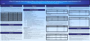
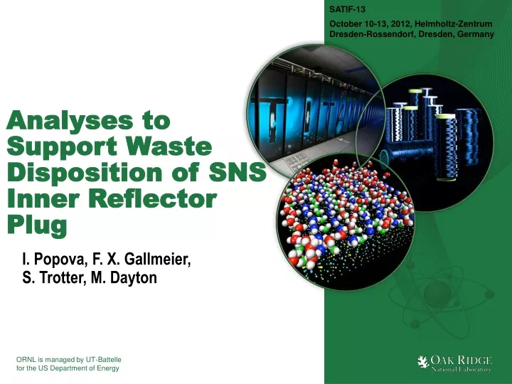
SATIF-13 October 10-13, 2012, Helmholtz-Zentrum Dresden-Rossendorf, Dresden, Germany Analyses to Support Waste Disposition of SNS Inner Reflector Plug I. Popova, F. X. Gallmeier, S. Trotter, M. Dayton
SNS layout • The Spallation Neutron Source in Oak Ridge, Tennessee, is an accelerator driven neutron scattering facility for materials research • SNS operates presently at up to 1.4 Megawatt (MW) proton beam power incident on a mercury target • Target building is designed to house 24 instruments • Presently 19 instruments are operating • 10 years beam on target
Introduction • According to the SNS operations plan Target System components are replaced: • To avoid excessive degradation of components materials – target vessels and proton beam windows; • When beam line optical components are ready to be installed Core Vessel Insert (CVI) plugs are extracted; • When reach planned end-of-life – Inner Reflector Plug (IRP). • Components must be: • Safely removed; • Placed in containers for storage on site in order to cool down; • Placed into shipping container packages to transport off-site.
Introduction • Inner Reflector Plug (IRP) is a central component of the SNS target monolith that is exposed to high-level radiation fields • Builds up significant activity • IRP needs to be replaced due to damage of structural materials caused by high particle fluxes, which reflects in the moderator poisoning • Life-time of IRP was assumed to be about 40,000MWh • IRP will be extracted from the target monolith and segmented into three components, each which will be disposed separately • Scheduled for replacement in March, 2017
Introduction Upper Segment is pulled into cask
Introduction • Neutronics analyses for IRP deposition are performed to: • Predict isotope composition for spent structures to support waste characterization and transportation analyses; • Predict dose rates after cool down; • Ensure choice of proper shipping container/package; • Develop shielding for container/package; • Perform transport analyses with real irradiation history for chosen container/package • Analyses are performed for each segment
Methods and Codes • Reaction rates and neutron fluxes below 20 MeV are calculated using MCNPX • Calculated results are fed into an Activation Script that provides the interface between MCNPX and the transmutation code CINDER’90 • The isotope inventory is obtained for the date of provisional transport of the package, if component has few materials ALLCODE is applied • Photon spectra are extracted by the GAMMA_SPECTRA script from the transmutation analyses output and formatted into a source description for MCNPX • Dose rates are calculated in the package vicinity using MCNPX • Report is generated
Methods and Codes • The latest 3D as-built target station and proton beam window model in MCNPX language are used • Effective dose rates are obtained by folding fluxes with flux-to-dose conversion coefficients, which are taken from standardized neutron and gamma flux-to-dose conversion coefficient libraries for the SNS • 2D mesh-tallies were defined in the vertical and horizontal planes • Surface tallies were set at requested key locations • For waste classification purposes a report containing isotope inventory, dose rates at specified locations is generated
Waste characterization • Report for waste management contains: • History of irradiation; • Radionuclide inventory; • Time line of component activity after beam termination; • Gamma dose rate contour plots; • Predicted dose rates at locations required by the U.S. Department of Transportation (DOT); • Distances from the side and the bottom of the spent component package for which the dose rates fall below 100 mrem/hr and 5 mrem/hr
Geometry • Large component - the IRP is cylindrical and about about 39” (100-cm) in diameter • Split into three segments, each segment will be disposed separately
Geometry • The SNS as-built target station model • Target module • Cylindrical IRP, including beryllium and steelreflectors andmoderators • Cylindrical outerplug, and theproton beamwindowassembly
Analyses • Analyses are performed for 40,443MWh distributed over 11 years of operation • Isotope inventories are presented for up to one year of cooling down • Dose rates are calculated for 100, 182 and 365 cool down for the top and for the middle segments • Dose rates are calculated for 100 days for the lower segment
IRP top segment Material is stainless steel 316 MCNPX model
IRP middle segment Material is stainless steel 316 MCNPX model
IRP lower segment Material is stainless steel 316
IRP lower segment • Beryllium reflector • Stainless steel reflector • Aluminum enclosure • Four moderators • Aluminum • Cadmium • Gadolinium • Stainless steel piping • Stainless steel shielding Moderators Moderators Shielding Aluminum enclosure Beryllium reflector Stainless steel reflector
IRP lower segment • The most irradiated segment • Complex geometry • Over 700 cells • Transformations • For residual analyses • Small cells with insignificant distribution were omitted • Due to limitation in the MCNPX source description, two decay gamma sources were prepared • Two transport simulations were performed • Results from the analyses were combined
Conclusions • An accurate estimate of the radionuclide inventory and the dose rates associated with radiation fields of the spent IRP were performed • Awaiting characterization and classification of each segment and to determine the appropriate storage and transport package. • Radiation fields at 30-cm from IRP lower segment after 100 days cool down are above 1000Rem/h.