Download
1 / 52
520 likes | 550 Views
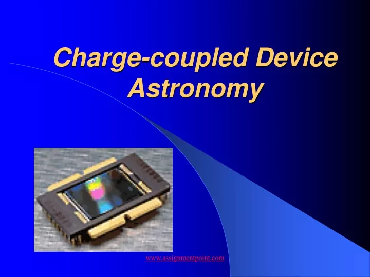
Charge-coupled Device Astronomy. Optical Sensors used in Astronomy. Human Eye For most of history the practical sensor has been the human eye. Limited by Sensitivity Physiological considerations and human subjectivity, placed serious limits on what could be discovered. Photographic Films

E N D
Charge-coupled Device Astronomy www.assignmentpoint.com
Optical Sensors used in Astronomy • Human Eye • For most of history the practical sensor has been the human eye. • Limited by Sensitivity • Physiological considerations and human subjectivity, placed serious limits on what could be discovered. • Photographic Films • The advent of photography in the last century was a monumental step forward in astronomy • It has the ability to record “unseeable” objects with long exposure times • Despite improvements, its efficiency remains very low. • For every 100 photons that strike the film, at best only three or four react with the silver in the film’s emulsion • Reciprocity failure www.assignmentpoint.com
My Telescope “1979” www.assignmentpoint.com
Optical Sensors used in Astronomy • Charged Coupled Device (CCD) • With better than 20% efficiency, they quickly won over the astronomical community • There sensitivity extends into the infrared spectrum • Its response to light is a linear function of incident flux and exposure time. • There is no reciprocity failure as encountered in long duration astrophotographs www.assignmentpoint.com
A CCD camera can provide a personal window to the universe or total frustration www.assignmentpoint.com
CCD Camera “Buzz” Words • CCD Arrays • Sampling • Pixels • Sensitivity • Pixel Binning • Blooming vs. Anti-Blooming • Readout Noise • Gain • Thermal Noise • Quantum Efficiency www.assignmentpoint.com
The first questions you should ask yourself • What kind of imaging are you interested in doing • The selection of your camera depends strongly on whether you want a system tuned for planets or deep-sky objects. In most cases your telescope and mount will make this choice for you. • While a deep-sky system can certainly record planets, and a planetary system can image galaxies, the best results almost always come from systems customized for a particular task. www.assignmentpoint.com
Deep Sky Imaging • The DEEP-SKY Camera must be: • Sensitivity • Low-noise • Some means of cooling the CCD • Peltier • Multi-pinned-phase mode (MPP) • A large detector (number of pixels verses pixel size) • 600 pixel-square array with 20 micron pixels • 1024 pixel-square array with 10 micron pixels www.assignmentpoint.com
Planetary Imaging • Different rules apply for planetary work • Dealing with bright objects • Short exposure times – No cooling required • Planets can be imaged using very small CCD arrays • Small arrays have an advantage in that their readout time is more rapid than larger arrays • Rapid readout facilitates taking many exposures, so you can be selective about which ones you keep www.assignmentpoint.com
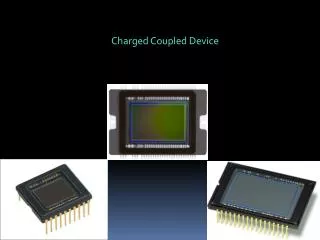
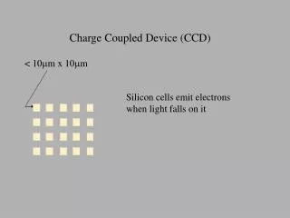
CCD Array Sensor www.assignmentpoint.com
Imaging Questions • Why do the stars look square in my images? • Why do my exposures times have to be so long to get any signal? • What is the size of my field of view? • These questions illustrate the three major issues of matching a telescope to a CCD array • Sampling • Pixel Sensitivity • Field of View www.assignmentpoint.com
Sampling • A CCD image is made up of tiny square-shaped pixels. • Sampling refers to how many pixels are used to produce detail. • Each pixel has a brightness value that is assigned a shade of gray color depending on how many photons strike the pixel during an exposure. • Since pixels are square, the edges of features in an image will have a stair-step appearance. • The more pixels and shades of gray that are used, the smoother the edges will be. www.assignmentpoint.com
Sampling • The following formula can be used to determine sky coverage per pixel with any given pixel size and focal length: (Sampling in arcseconds) = 206.265 / (focal length in mm) * (pixel size in microns) Or (Sampling in arcseconds) = 8.12 / (focal length in inches) * (pixel size in microns) Undersampled Oversampled www.assignmentpoint.com
The CCD user has some control over focal length and pixel size Average seeing is between 3 to 5 arcseconds A good rule of thumb to avoid undersampling is to divide your seeing in half and choose a pixel size that provides that amount of sky coverage Sampling www.assignmentpoint.com
Pixel Sensitivity • The larger the pixel, the more sensitive the camera will be for any given focal length. • Under excellent seeing conditions, a camera with 24 micron pixels on a telescope of 2000 mm focal length will produce images that are very close to being undersampled. • For bright planets, oversampling will provide better resolution and it will help cut down the glare that can saturate the CCD pixels. • On the other hand, for faint deepsky objects like galaxies or nebula, moving toward undersampling will give better sensitivity, allowing shorter exposure times. • If an image is to be sharpened, you will get the best results with images that are well sampled. www.assignmentpoint.com
Pixel Binning • Most CCDs have the ability to clock multiple pixel charges in both the horizontal and vertical direction into a single larger charge or “super pixel”. • The super pixel represents that area of all individual pixels contributing to the charge. • 2x2 binning increase the sensitivity by a factor of 4, but the resolution of the image is cut in half. www.assignmentpoint.com
Bloomimg vs. Anti-Blooming www.assignmentpoint.com
Bloomimg vs. Anti-Blooming www.assignmentpoint.com
Readout Noise • Readout noise is specified both for the CCD sensor and the total system. • First, there is not perfect repeatability each time charge is dumped out of the CCD and digitize. • Conversions of the same pixel with the same charge will not always yield the same result from the A/D. • The second aspect of noise is the injection of unwanted random signals by the sensor and electronics which ends up getting digitized along with the pixel charge. • Read-out noise is often expressed in the unit known as an electron. • Cameras geared towards amateur astronomy have read noise between 10 and 100 electrons per pixel. www.assignmentpoint.com
Thermal Noise • Thermal Noise • The most common term used when describing thermal noise is dark current • Thermal noise charges, again expressed as electrons, are generated in a CCD camera regardless as to whether it is exposed to light or complete darkness • Thermal noise is temperature dependent • The higher the temperature of the CCD the higher the thermal noise • The lower the temperature of the CCD the lower the thermal noise • Thermal noise is lowered by decreasing temperature of the CCD. The read out noise stays the same www.assignmentpoint.com
Thermal Noise www.assignmentpoint.com
System Gain • System gain is a way of expressing how many electrons of charge are represented by each count (ADU). A gain of 2.5 electrons/ADU indicates that each count or gray level represents 2.5 electrons. • Kodak KAF-0400=85000/2.5=34000 counts. • As long as the total well depth of a sensor can be represented, a lower gain is better to minimize the noise contribution from the electronics and give better resolution. • Gains which are unnecessarily high can result in more digitization noise, while gains which are too low will minimize noise at the expense of well depth. • For example, a gain of 1.0 would certainly minimize the electronics contribution to noise, but would only allow 65,536/1.0 = 65,536 electrons of the 85,000 to be digitized. • System gains are designed as a balance between digitization counts, digitization noise, and total well depth. www.assignmentpoint.com
Digitization • Digitization, also referred to as analog to digital conversion, is the process by which an analog charge from the CCD is translated into a binary form used by the computer. • The term binary refers to the base 2 number system used. • A 12 bit camera system will output 4096 levels. • A 14 bit system will output 16384 levels. • A 16 bit camera will output 65536 levels. • The higher the digital resolution, the slower the system throughput. www.assignmentpoint.com
Dynamic Range • The dynamic range is often represented as a log ratio of well depth to the readout noise in decibels. • For example, a system with a well depth of 85,000 electrons and a readout noise of 12 electrons would have a dynamic range = 20 log (85,000/12), or 77dB. The higher the number the better. • This ratio also gives an indication of the number of digitization levels that might be appropriate for a given sensor. A sensor with a well depth of 35,000 electrons and with 15 electrons of read noise would yield a ratio of 35,000/15=2333. Unless there is a desire to resolve this noise with a 16 bit system into 65,536 gray shades, a 12 bit system with 4096 levels would be more than adequate for this sensor. www.assignmentpoint.com
Quantum Efficiency • The quantum efficiency (Q.E.) of a sensor describes its response to different wavelengths of light www.assignmentpoint.com
Charge Transfer Efficiency • As each charge is transferred, not every electron will be carried along with perfect efficiency. Some get "left behind" or trapped. • Charge Transfer Efficiency of 0.99997 can be thought of as 2.5 electrons out of 85,000 electrons not transferred or "lost in the shuffle". • Since the CTE is sensor dependent, all manufacturers of imaging systems using the same sensor will start with the same efficiency specification. Improper camera system design can cause less than optimum charge transfer efficiency. www.assignmentpoint.com
Data Rate and Transfer Rate • The key consideration here is, "How long from the time the shutter closes do I have to wait to see the image?" • The shorter this time is, the easier to focus the system and more enjoyable the CCD imaging experience will be. • Also, dark count continues to build during the delay and readout. The longer the actual charge transfer time from the CCD, the greater the top to bottom dark count gradient. www.assignmentpoint.com
Other Factors • Weight • Electronics Modules • Surface mount technology • Stay away from cameras with bulky external control boxes • Number of camera connections • Camera start-up procedures • Peltier Cooler • Starlight Xpress – just plug in he camera • SBIG – Controlled by software • Cooling Fans • Can induce vibrations www.assignmentpoint.com
Other Factors • Is the software user friendly • Drop-down menus • Dialog boxes • Keyboard shortcuts • Learning curve of the camera • Large instruction manuals • Using your camera should be an enjoyable experience www.assignmentpoint.com
Basic Imaging Concepts www.assignmentpoint.com
More “Buzz” Words • Bias Frames • Light Boxes • T-Shirt Flats • Flat Fields • Dark Frames • Raw Imagines • Calibrated Image • Signal vs. Noise www.assignmentpoint.com
Bias Frames • Astronomers make bias frames to capture the bias level. • Bias frames represent noise levels that occur on a CCD detector when placed in total darkness with an integration time of zero. • These frames represent the minimum noise generated by the camera electronics as pixel values are read from the CCD array. • This bias level can fluctuate because of things that happen every time the CCD is read out or because extraneous signals are added to the bias level. These un-patterned events can originate in power supplies, nearby electronics, motors, and radio-frequency interference from computers and monitors. • The noise in these bias frames is extremely low; so many CCD imagers do not bother to apply them to their images. www.assignmentpoint.com
Why take Bias Frames? • They give you a history of your cameras operational functionally. Noise level changes Interference • They are needed if you intend to do astrometry, photometry or to get the best results from your images. NOTE: SBIG cameras add a 100-unit pedestal to each Bias, Dark, Flat- Field, and Light frame. This pedestal value is subtracted by CCDSoft during the data reduction process. This will need to be subtracted manually with other IP programs. www.assignmentpoint.com
Bias Frame DemoRead Out Noise Demo www.assignmentpoint.com
Dark Frames • Even when a CCD array is placed in total darkness, individual pixels build up a charge over time. Most of this noise is generated by heat, and is called thermal noise or dark current. Lowering the temperature of the CCD array can reduce this thermal noise. The colder you can make the array, the lower the thermal noise. www.assignmentpoint.com
Dark Frames www.assignmentpoint.com
Cosmic Rays www.assignmentpoint.com
Flat Fields • Taking an image of an evenly illuminated surface will create a flat field frame. Even though the CCD detector has been exposed to an evenly illuminated surface, the charge built up on each pixel can vary; flat fields are used to correct for these variations. There are other circumstances, which can help create these variations such as internal reflections, central obstructions and dust on optical surfaces. NOTE: CCD detectors and their electronics have natural variations in the full-well depth and gain settings so the average value of the brightest area in a flat field should fall between 33% and 50% of the CCD’s saturation point. www.assignmentpoint.com
How do you find the saturation point? Full Well Capacity / Gain = The Saturation Point For the ST-7E ABG 50,000 / 2.3 = 21,740 21,740 * .33 = 7,250 21,740 * .50 = 11,000 www.assignmentpoint.com
Flat Fields www.assignmentpoint.com
Flat Field Demo www.assignmentpoint.com
Reduction of Dark and Flat Fields www.assignmentpoint.com
Dark Frame Subtraction Demo www.assignmentpoint.com
The Importance of Average Stacking • Averaging reduces noise by the square root of the number of frames you average. • 4 images = noise reduced by a factor of ½ • 9 images = noise reduced by a factor of 3 • 20 images = noise reduced by a factor of 4.5 1 image 3 images 10 images www.assignmentpoint.com
Image Stacking Demo www.assignmentpoint.com
Mosaic Demo www.assignmentpoint.com
Images www.assignmentpoint.com
Images www.assignmentpoint.com
Images www.assignmentpoint.com
Calculated Measurement Screen www.assignmentpoint.com